Product Manual ALR2-3
ALR 110F – 150F
37
Chilled Water Piping
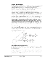
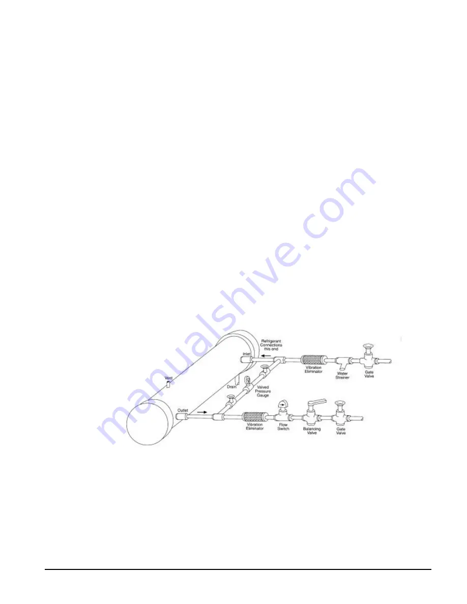
Flush the system water piping thoroughly before making connections to the unit evaporator. A
strainer of 40 mesh should be installed in the return water line before the inlet to the chiller. Design the
water piping so the chilled water circulating pump discharges into the evaporator inlet.
Connect the return water line to the evaporator inlet connection (the connection closest to the
compressors). Connect the supply water line to the evaporator outlet connection.
Install a flow switch in the horizontal piping of the supply (evaporator outlet) water line.
Provide drain connections at low points in the system to permit complete drainage of the system. Air
vents should be located at the high points in the system to purge air out of the system. A vent
connection on top of the evaporator vessel permits the purging of air out of the evaporator. Purge air
from the water system before unit start-up to ensure adequate flow through the evaporator.
Pressure gauges should be installed in the inlet and outlet water lines to the evaporator. Pressure drop
through the evaporator should be measured to calculate proper flow as determined from Figure 5.
Vibration eliminators are recommended in both the supply and return water lines.
Chilled water piping should be insulated to reduce heat loss and prevent condensation. Chillers not
running in the winter should have their water systems thoroughly drained to protect against freezing.
If the chiller operates year round, or if the system is not drained for the winter, the chilled water piping
exposed to outdoor temperature should be protected against freezing. Wrap the lines with a heater
cable and add proper amount of glycol to the system to further protect the system during low ambient
periods.
Chilled Water Piping
On ALR 110F through 150F the thermostat sensor is factory mounted in the leaving water well. If an
optional high return water sensor is provided, install sensor bulb in a field supplied tee or strap to the
outside of the water line.
Figure 23, Typical Chilled Water Piping
Series Compared to Parallel Operation
Consider system pressure drop when designing the water piping. Parallel piped systems have half of
the total system flow going through the evaporator of each chiller, reducing the individual unit and
total system pressure drop.
Series piped evaporators require that the total system water flows through both evaporators. Not only
is the pressure drop through each evaporator increased but the pressure drops must be added
together to obtain the total evaporator pressure drop. Series piped evaporators normally require larger
circulating pumps for the chilled water system.

