IM 685 / Page 17
Flame Rod Installation
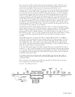
The flame rod must be disassembled from its porcelain insulator for removal or installation. Remove the
two nuts on the threaded end of the flame rod, pull the rod out of the insulator, and then remove the
insulator by loosening its clamp screw.
Ignition Electrode Adjustment
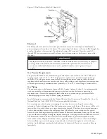
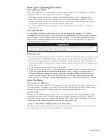
The gun assembly is removed for ignition electrode inspection or service. When correctly adjusted the
ignition electrode insulator will be concentric with the hole it passes through, the end of the insulator
will be flush with the outside surface of the gun disc, the electrode tip will point toward the 0.086 inch
diameter alignment hole, and there will be a 0.09 inch spark gap to the gun disc (see Figure 9). The
ignition electrode can be removed by loosening the clamp screw and sliding the entire assembly through
the disc hole.
Air and Gas Adjustments
The burner has been adjusted and tested at the factory with accurate instruments. There should not be a
need to readjust the burner after the unit has been installed.
Verify that the gas supply pressure is correct, the electrical power is correct, and test the burner
thoroughly. Do no make adjustments unless there is a clear indication that there is a problem, and
proper instruments are available so the adjustments can be made correctly.
Gas Supply Pressure
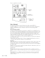
The maximum pressure rating of the combination gas control(s) used on this burner is 0.50 psi (13.9 in.
w.c.), as measured at (2), Figure 16a. If the gas supply pressure is higher than this an additional
regulator must be installed so the pressure will not exceed 0.50 psi.
Many gas burner problems are due to gas supply pressure problems. High or low gas pressures can cause
nuisance lockouts of the flame safeguard and combustion problems. Low gas pressure will reduce the
heat output of the furnace, and if extreme, can cause combustion problems and flame safeguard
lockouts. Every gas supply system has a high pressure regulator somewhere upstream. Perhaps it is at the
meter and adjusting the outlet pressure is not an option, the following discussion on the "High Pressure
Regulator" would still apply.
High Pressure Regulator
If a high pressure regulator is included as part of the burner gas train or is included elsewhere in the gas
supply line, it should be adjusted so the pressure at the inlet tap to the combination gas valves is 7.0 in.
w.c. The inlet tap is (2) on Figure 16a. Check that the pressure is relatively consistent as the firing rate
changes. If any other equipment is served by that same gas line or pressure regulator, check that the gas
pressure also remains relatively consistent when that equipment is turned on and off. Verify that the
regulator closes off tightly at zero flow by observing that the pressure does not creep up when the unit is
off. If it does, excessive pressure will have built up over the off period, possibly exceeding the pressure
rating of the combination gas controls, and causing other problems at light off.
Gas Adjustments
See the sections on "Gas Valve Pressure Regulator Adjustment", "Gas Supply Pressure", and "High
Pressure Regulator". The gas flow rate is determined by the gas pressure and a characterized element
within the modulating gas valve. The stem of the valve connects to the bracket that positions it with
lock nuts that are adjusted at the factory and determine the minimum firing rate of the burner. Other
than gas pressure adjustments, this is the only adjustable control of the gas. Adjusting the minimum rate
is not intended to be a routine field adjustment. Properly adjusting the minimum rate requires clocking
a gas meter at very low flow rates, or connecting a test flow meter into the gas train.
Air Adjustments
Airflow and the resultant combustion characteristics have been preset and tested at the factory and no
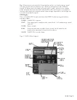
further adjustments should be required. Airflow to the burner is determined by the characterized plate
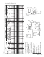
on the air valve outlet (1) and an adjustable plate (2) on Figure 10a. The adjustable plate can increase or
decrase airflow across the entire stroke of the valve. If burner airflow is in question, measure the static
pressure at Ports (4) and (5), Figure 16, and compare those readings with Columns 6 and 8 in Table 5.
A significant difference should be checked out.


