background image

Summary of Contents for SEASONCON ALP-045C

Page 1: ......

Page 2: ......

Page 3: ...ll of lading to insure a complete ship with the power supply available Physical damage to unit after ment All units should be carefully inspected for damage upon acceptance is not the responsibility of McQuay arrival All shipping damage should be reported to the car NOTE Unit shipping and operating weights are available rier and a claim should be filed The unit serial plate should in the physical ...

Page 4: ...2 Units must not be Installed in a pit that is deeper than the height of the unit 3 Minimum clearance on each side is 12 feet when installed in a pit 6 FT MIN CLEARANCE FOR AIR INLET VIBRATION ISOLATORS Vibration isolators are recommended for all roof mounted in stallations or wherever vibration transmission is a considera tion Table 1 lists spring isolators for all ALP unit sizes Figure 4 shows i...

Page 5: ......

Page 6: ...s The liquid line should be sized for a pressure drop not to exceed the pressure equivalent of 2 F 6 psi saturated temperature The liquid line s on all units must include a liquid solenoid valve wired into the circuit as shown on the applicable unit wiring diagrams The control circuit for all compressors has been de signed to include a pumpdown cycle The use of a liquid line solenoid is required f...

Page 7: ...ressor circuit 2 Trap for double suction riser should be as small in horizontal direction as fittings will allow 3 The thermal expansion valve equalizer line should be placed just past the thermal sensing bulb on the side or top of the pipe 4 A separate expansion valve is required for each distributor and mounted per manufacturer s recommendations See additional notes under recommended line sizes ...

Page 8: ...dbooks should where applicable be followed in the design and In stallation of piping 886 580896A 06 i 886 580896A 09 1 1 a 886 580896A 10 1 s 1 s l 2 886 580896A 10 1 l a l 2 886 580896A 11 1 1 I 23oc 182 886 580896A 11 1 1 NOTE Larger capacity expansion valve in liquid line accessory kit is used for circuit 2 _ _ 1 a 1 a 1 Yi 1 h 1 a 1 1 h 1 a 1 1 1 h 1 t s 1 a 1 LIQUID LINE COMPONENTS McQuay has...

Page 9: ...rant cylinder and the valve Then open the valve to the mid position If the system is under a vacuum stand the refrigerant drum with the connection up and open the drum and break the vacuum with refrigerant gas With a system gas pressure higher than the equivalent of a freezing temperature invert the charging cylinder and elevate the drum above the condenser With the drum in this position valves op...

Page 10: ......

Page 11: ......

Page 12: ......

Page 13: ......

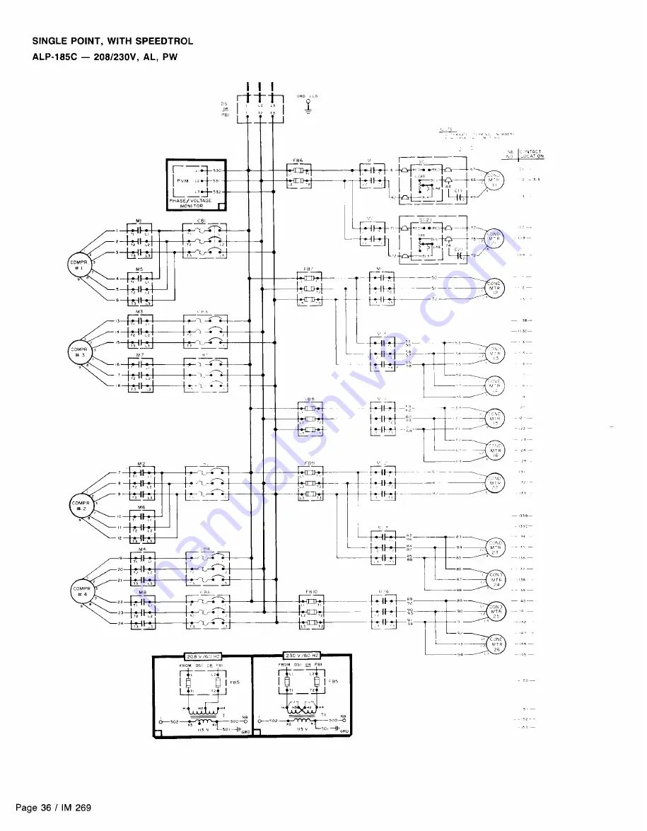
Page 14: ...is ordered three power connections one per compressor circuit plus one for condenser fans are required and wiring with the unit is sized in accordance with the National Electrical Code Separate field supplied discon nects are required for each of the three circuits A single power block is provided for all of the condenser fans and the optional 115V control transformer CAUTION Internal power wiring...

Page 15: ......

Page 16: ......

Page 17: ......

Page 18: ... codes required for a safe and proper installation FLOW SWITCH FOR CHILLED WATER APPLICATIONS A WATER FLOW SWITCH MUST BE MOUNTED in either the entering or leaving water line to insure that there will be adequate water flow and cooling load to the evaporator before the unit can start This will safeguard against slugging the compressors on startup It also serves to shut down the unit in the event t...

Page 19: ...PLES OF OPERATION Figure 14 Major Component Locations The figures below illustrate component locations within the unit for each unit size COMPRESSOR No 1 COMPRESSOR No 1 I I L J COMPRESSOR No 2 TOP VIEW OF UNIT COMPRESSOR No 2 J _ COMPRESSOR No 4 CONTROLCENTER All electrical controls are enclosed in a weatherproof control center with keylocked hinged access doors The control center is composed of ...

Page 20: ......

Page 21: ......

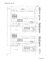
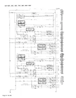
Page 22: ...LP1 closes This energizes the compressor starting relay R9 start ing the compressor via the compressor contactors Ml and M5 Closing the R9 contacts also energizes the condenser fan motor contacts Ml 1 M12 Ml3 and M14 starting the fan motors As additional stages of cooling capacity are required the unit thermostat energizes the liquid line solenoid valve SV2 of the refrigerant circuit X2 After the ...

Page 23: ......

Page 24: ......

Page 25: ......

Page 26: ......

Page 27: ......

Page 28: ......

Page 29: ......

Page 30: ......

Page 31: ......

Page 32: ......

Page 33: ......

Page 34: ......

Page 35: ......

Page 36: ......

Page 37: ......

Page 38: ......

Page 39: ......

Page 40: ......

Page 41: ......

Page 42: ......

Page 43: ......

Page 44: ......

Page 45: ......

Page 46: ......

Page 47: ......

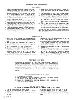
Page 48: ...ry equipment for the installation Check to see that pumpdown switches PSI and PS2 are in the manual pumpdown open position Throw the emergency stop switch S 1 to the on position If pressures on the low side of the system are above 60 psig the unit will start and pump down After the compressor lockout timer TD1 has timed out start 7 8 9 the system by moving pumpdown switches PS1 and PS2 to the auto...

Page 49: ...necessary other than keeping the oil clean and dry If the system contains a refrigerant charge close the suc tion valve and reduce crankcase pressure to 1 to 2 psig Stop the compressor and close the discharge valve Add the required amount of oil During the period the com pressor is exposed to the atmosphere the refrigerant will generate a vapor pressure retarding the entrance of con taminants Befo...

Page 50: ...ant piping by moving pumpdown switches PS1 and PS2 to the manual pumpdown position THERMOSTATIC EXPANSION VALVE The expansion valve is responsible for allowing the proper amount of refrigerant to enter the evaporator regardless of cooling load It does this by maintaining a constant superheat Superheat is the difference between refrigerant temperature as it leaves the evaporator and the saturation ...

Page 51: ...hip and in warranty credit will be issued on customer s purchase order APPENDIX STANDARD CONTROLS NOTE PERFORM AN OPERATIONAL CHECK ON ALL UNIT SAFETY CONTROLS ONCE PER YEAR OIL PRESSURE SAFETY CONTROL The oil pressure safety control is a manually resettable device which senses the differential between oil pressure at the discharge of the compressor oil pump and suction pressure inside the compres...

Page 52: ...s PSI and PS2 to the auto pumpdown posi of Hg to 100 psig and an adjustable differential of 6 to 40 tion evaporator pressure will rise The highest evaporator psig To check the control unit must be running move the pressure reached before compressor restart is the cut in set pumpdown switch es PS1 and PS2 to the manual pump ting of the control down position As the compressor pumps down condenser Th...

Page 53: ...mpressor When R9 is energized another set of contacts will shunt around TD1 allowing TD1 to reset open for timing out the next compressor cycle To check the control the compressor must be running in itially Move the pumpdown switch PS1 or PS2 to the manual pumpdown position Immediately after the compressor has stopped running move the pumpdown switch back to the auto pumpdown position The compress...

Page 54: ...he low pressure control open After about 2 minutes the time delay will open and de To check the control turn off all power to the unit and remove the wire s leading to the terminals of the low pressure control s LPl and LP2 Remove power to the compressor and jumper across terminals 48 to 50 for circuit 1 and 78 to 80 for circuit 2 Switch the pumpdown switch es PS1 and PS2 to the auto pumpdown posi...

Page 55: ... McQuay of fers is factory set to begin opening at 58 psig 32F for R 22 when the air charged bulb is in an 80F ambient temperature The bulb can be mounted anywhere as long as it senses a fairly constant temperature at various load conditions The compressor suction line is one such mounting location It is generally in the 50F to 60F range The chart below indicates that when the bulb is sensing 50F ...

Page 56: ......

Page 57: ......

Page 58: ...tion 4 Reset thermostat setting to fit application 1 Erratic water thermostat 1 Replace 2 Insufficient water flow 2 Adjust gpm 1 Clogged suction oil strainer 2 Excessive liquid in crankcase 3 Oil pressure gauge defective 6 Oil pump reversing gear stuck in wrong position 4 Low oil pressure safety switch defective 5 Worn oil pump 7 Worn bearings 8 Low oil level 6 Reverse direction of compressor rota...

Page 59: ...winding start systems 1 Operating beyond design conditions 2 Discharge valve partially shut 3 Blown valve plate gasket 1 2 3 4 5 6 7 Check supply voltage for excessive line drip Replace compressor motor Check all connections and tighten See Corrective Steps for high discharge pressure Check supply voltage Notify power company Do not start until fault is corrected Provide ventilation to reduce heat...

Reviews: