CHECKING CONTROLS
All controls are checked and adjusted prior to leaving
the factory. However, after the unit has operated satis-
factorily for a reasonable length of time, a check of
the operation and safety controls can be made as
indicated below:
A.
B.
C.
Oil
Pressur e
Safety Switch
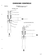
The oil failure pressure switch is activated by
pressure differential between the oil pump pres-
sure and the crankcase pressure. Upon start up,
the normally closed pressure actuated contact of
this control opens when the pressure differential
increases to about 15 psig. If oil pressure does not
reach this differential, the thermal time delay re-
mains energized and opens a bi-metallic safety
contact, de-energizing the complete control circuit.
If pressure reaches the prescribed differential
within 120 seconds, the thermal time delay is de-
energized and the control circuit remains closed.
If, during the operation, the oil pressure differen-
tial falls below 10 psig, the thermal time delay is
again energized and the control will shut down the
compressor.
To check the control, trip the circuit breaker to
the “off’ position. Throw control circuit to “on”
to pull in contactor. The contactor should drop out
after approximately 120 seconds. After checking
the control, wait approximately 2 to 3 minutes for
the bi-metal thermal element to cool and then reset
control manually. The compressor can then be
started. Repeated successive operations of the
control will require a longer period before it can
be reset, since the bi-metal thermal element will
get hotter and will take more time to cool.
High Pressure Control
The high pressure switch will shut down the com-
pressor and close the liquid line solenoid valve
when the compressor discharge pressure reaches
390 psig. To check the control, shut down the con-
denser fan and observe the cut out point. During
testing, stand by the system on-off switch to shut
down the unit should the safety device malfunc-
tion. Be sure the gauges used are accurate. The
high pressure relief valve is set for 425 psig.
Lo w Pressure Control
This pressure switch is connected to the low side
of the system and its purpose is to shut down the
D.
E.
compressor at the end of the pumpdown cycle. It
will open at 35 psig and automatically reset at
approximately 60 psig. The control can be checked
by throwing the individual pumpdown switches to
the manual position and observing the cutout point
on the gauge.
Freezestat Thermostatic Contro
l
(TC2)
This control has a bulb located in a well in the
water piping leaving the cooler. To check this con-
trol, remove the operating thermostat bulb in enter-
ing water to chiller from its well to prevent it from
shutting down the system. Then drop the water
temperature until the freeze control in the leaving
water
of
chiller shuts down the system. The control
should be set to cut out when the water tempera-
t u r e l e a v i n g t h e c h i l l e r r e a c h e s 3 6 F 1F.
Thermostat (TC1)
The thermostat supplied on all packaged water
chillers are factory calibrated for use in the return
water line to the cooler inlet. The thermostat bulb
is installed in a well in the return water line in
order to be more stable under temperature changes
due to load conditions. Figure 9, Page 24, illus-
trates the recommended method of installing the
bulb and well in the return water line. The return
water does not change temperature as rapidly as
the outlet
becaus e
of the “fly wheel effect” of the
total water system. This results in a stable, non-
recycling control of the outlet water temperature.
Normally the thermostat requires no adjustment
in the field other than the dial setting for the re-
quired control point. The control is preset at the
factory to maintain a 44F average leaving water
temperature throughout the loading and unloading
sequence of the unit, based on a full load cooling
range of 10F. It should be realized, however, that
there will be a fluctuation in the leaving water
temperature as the unit cycles, unloads and loads.
The magnitude of fluctuation will decrease as the
n u m b e r o f c a p a c i t y c o n t r o l s t e p s i n c r e a s e s .
On a two stage thermostat, the dial setting indi-
cates the average leaving water temperature that
the control will maintain. At a 44F setting, the
high stage should actuate at approximately 5lF
r e t u r n w a t e r and
41 F
leaving
based o n 10
cooling
ra
nge .
The low stage will open at 46F return or
4 1 F l e a v i n g
T D a t 5 0 % c a p a c i t y ) .
Page 20


