CHECK
ING
VALVE CHECKING AND SETTING
The SEASONTROL head pressure control valves are
factory set and checked to maintain a minimum head
pressure equivalent to 90F condensing. The valves
have a nominal 15 psig modulating range between fully
open and fully closed positions. Typical settings for
R-22 use is to have the valves modulate between 160
and 175 psig. This will maintain a nominal 90F con-
densing.
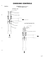
Referring to the sectional diagrams, it is to be
noted
that on pressure increase on the system, the pressure
will tend to compress the bellows and the valve stroke
will be up or toward the adjustment end of the valve.
This also applies to the 237 series valves. The 239
series, or liquid valves, open on pressure rise. The
valve travel is a nominal one tenth inch for all models.
As indicated in the diagrams, the adjustment of the
nut in a clockwise direction will increase the modu-
lating pressure point. A wide bladed screwdriver or
similar tool inserted into the nut slot may be used for
making the adjustment. Turning the adjustment nut
clockwise raises the control point.
The modulating pressure point and range may be
checked as follows:
A. Make up a “depth gauge” for inserting through the
adjusting nut opening and long enough to hit the
CONTROLS
B.
C.
D.
E.
bottom of the bellows section as indicated in the
diagrams. A piece of insulated wire, 8 to 12
gauge, is a simple and convenient method to make
a gauge. Insert a piece of the wire into the valve
as shown in diagrams. Trim off insulation, for
about one inch of the end to be inserted, and at a
point just above the top of the valve at the other
end. Hold the gauge down lightly against the bel-
lows and sight along the top of valve.
A high side gauge should be connected to a line
so it can be brought to the valve area while valve
observations are being made.
Start up the unit and note pressures at which valve
bellows rise. We assume that the pressure was low
enough at start up so that the bellows is in the
down position. The test may also be done in re-
verse by running the system upto a high head pres-
sure, stopping the unit, and making observations
at what pressure the valve changes position.
The valves should he set so that tho movement of
both valves is through the same pressure range.
Be sure system has sufficient refrigerant before
assuming valves are out of adjustment.
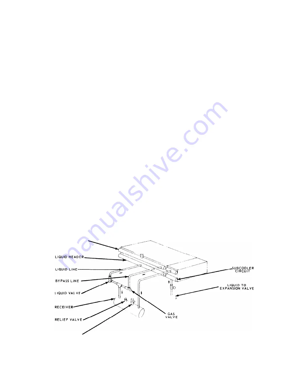
FIGURE 8A
SEASONTROL III
head pressure control
For operation at OF ambient.
H O T G A 5 H E A D E R
P U R G E V A L V E
Page 22


