FIGURE
1 0
A.
B.
C.
SYSTEM COMPONENTS
FIGURE 11
COMPRESSOR
D.
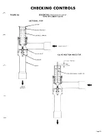
FS4-3 FLOW SWITCH
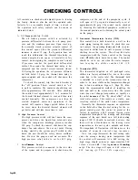
The reciprocating semi-hermetic compressor(s)
are complete with suction and discharge service
valves, integral force feed lubrication system, oil
sight glass, oil charging connection, crankcase
heater and initial oil charge.
T h e motor is of the hermetic induction type, 1750
rpm, gas cooled, with inherent
and/or supplementary overload
required. The standard unit is
the-line starting. Part winding
able as an option.
thermal protection
protection, where
wired for across-
starting is avail-
The compressor is pre-wired and ready to run.
Suction and discharge service valves are closed
during shipment and must be opened just prior to
start up. Gauge connections on suction and dis-
charge valves are closed when the valve stem is
back seated in the full open position. To increase
the life of any gauges supplied, the suction and
discharge valve should be back seated except when
readings are required. Always replace valve caps
with gaskets in place.
The safety
control
piping connection t o
t h e c o m -
pressor includes: the oil failure switch-high p r e s -
sure oil connection at the oil pump discharge; the
oil failure switch-low pressure connection at the
compressor crankcase; the high pressure safety
connection at the discharge manifold; and the low
pressure connection at the suction chamber on
the motor end of the compressor. Shut off valves
E.
F.
G.
VIEW FROM END OF COOLER
STRAIGHT PIPE
1
are never installed in these control lines.
The compressor is pre-charged with sufficient oil
for normal operation. In case oil is required. or if
unit requires additional oil after installation, the
compressor must be pumped down to near zero pres-
sure, valves closed, and oil charged through the
filler plug on the side of the compressor oil
sump.
The plug must be replaced with a sealer and leak
c h e c k e d
during operation. Precautions must b e
taken to prevent
air entry into crankcase or refrig-
erant system.
A compressor crankcase heater (energized by main
disconnect continually) is provided to minimize r e -
frigerant accumulation into the crankcase oil when
compressor is not in operation. Excessive refrig-
erant in the crankcase dilutes the oil, causing
excessive foaming, oil loss, and, in extreme cases,
bearing washout and possible failure. The heaters
are energized at all times. During prolonged shut-
down, when the electrical power may be shut off,
c l o s e the suction and discharge service valves to
prevent migration of the refrigerant to the oil and
reopen the valves just prior to start up. Also. allow
sufficient time for heater to boil refrigerant out of
c r a n k c a s e oil .
Except for minor repairs such as replacing a suc-
tion or discharge reed valve, the compressor is not
generally repaired in the field. Exchange comprcs-
sors are stocked in warehouses throughout the
country and the damaged compressor is turned in
for credit.
Page 25


