background image

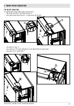
r

T

z

S

28

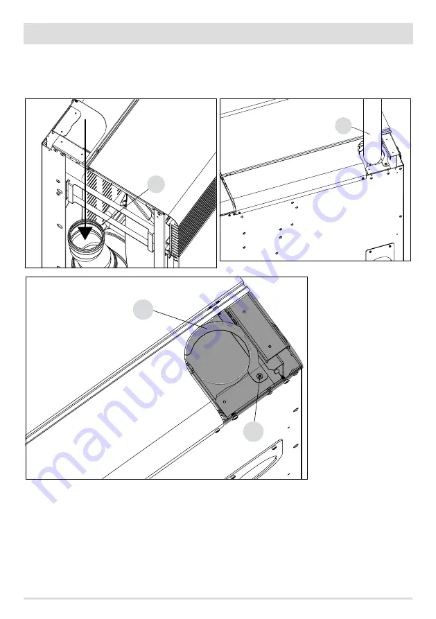
5 - SMOKE OUTLET CONNECTION

• 

insert the linear pipe “T” (not supplied) into the inlet “r” on the stove

• 

secure the pipe “T” to the stove using the hook “S” and screw “z”

Summary of Contents for MUSA Hydromatic 16 M1

Page 1: ...INSTALLATION GUIDE GB PELLET STOVE AKI Hydromatic 16 24 M1 PART 1 REGULATIONS AND ASSEMBLY Instructions in English ...

Page 2: ...RNINGS AND WARRANTY CONDITIONS 2 2 INSTALLATION 10 3 DRAWINGS AND TECHNICAL SPECIFICATIONS 19 4 UNPACKING 23 5 SMOKE OUTLET CONNECTION 26 6 CLADDING ASSEMBLY 29 7 OPENING THE DOORS 35 8 LOADING THE PELLETS 38 9 HYDRAULIC CONNECTION 40 10 ELECTRICAL CONNECTION 44 ...

Page 3: ...o part of this manual may be translated into other languages adapted and or reproduced even in part in other mechanical and or electronic form or media for photocopies recordings or other without the prior written authorisation of MCZ Group Spa The company reserves the right to make changes to the product at any time without prior notice The owner company reserves its rights according to law CARE ...

Page 4: ...ry or mental capabilities or lack of experience and knowledge if they have been given supervision or instruction concerning use of the appliance in a safe way and understand the hazards involved Children must not play with the appliance Cleaning and user maintenance shall not be carried out by children without supervision The user or whoever is operating the product must read and fully understand ...

Page 5: ... can generate an abnormal amount of unburnt gas with a risk of explosion in the chamber Accumulated unburnt pellets in the burner after a failed ignitions must be removed before lighting Failure to clean and maintain the brazier can result in improper running and explosions within the stove Make sure you remove and clear the holes in the brazier and any loose encrustations every time you empty the...

Page 6: ...t not be exposed to weathering It is recommended not to remove the feet that support the product in order to ensure adequate insulation especially if the flooring is made of flammable materials In the event of a malfunction of the ignition system do not force it on by using flammable materials Special maintenance must only be performed by authorised and qualified personnel Assess the static condit...

Page 7: ...ilers In the case of tests for any market surveillance or inspections by third parties please consider the following warnings To reach the declared performance levels the product must perform an operating cycle of at least 15 20 hours beforehand Set the average draught of the combustion fumes as specified in the technical product features table ThetypeofpelletsusedmustcomplywiththecurrentENISO1722...

Page 8: ...h the document given at the time of purchase to theTechnical Service Centre EXCLUSIONS The warranty does not cover malfunctions and or damage to the appliance that arise due to the following causes Damage caused during transport and or handling all parts that develop faults due to negligence or improper use incorrect maintenance installation that does not comply with the manufacturer s instruction...

Page 9: ...agreed conditions and in accordance with the fees in force for the work to be carried out The user will also be charged for any costs incurred to remedy the incorrect technical operations tampering or damage to the appliance not attributable to original faults Without prejudice to the legal or regulatory limits the warranty does not cover the containment of atmospheric and acoustic pollution Theco...

Page 10: ...cumulators included must not be collected recycled or disposed of with household waste at the end of their service life Improper management of waste electrical and electronic equipment batteries or accumulators can cause the hazardous substances contained within to leak out In order to avoid harming the environment or health the user is required to separate this equipment and or the batteries or a...

Page 11: ...tem the Products must be installed controlled and serviced by qualified personnel according to the instructions in this manual and in compliance with local laws and installation and maintenance standards in force in individual countries so as to provide an efficient heating system properly sized according to the needs of the home if the Products are thermally stressed constantly operating for seve...

Page 12: ...kg Toensuregoodcombustion thepelletsmustbestoredinadryplaceandprotectedfromdirt Pelletsareusuallysuppliedin15 kg bags therefore storing them is very convenient Good quality pellets guarantee good combustion thereby decreasing harmful emissions into the atmosphere Thepoorerthequalityofthefuel themoreoftentheinternalpartsofthebrazierandcombustionchamberneedto becleaned The main quality certification...

Page 13: ...heintegrityofthehome Installationoftheappliancemustensureeasyaccess to clean the appliance itself the smoke outlet pipes and the flue It is forbidden to install the stove in rooms with a fire hazard Installation in studio flats bedrooms and bathrooms is only permitted with sealed or closed appliances equipped with suitable combustion air ducting directly outside Always maintain adequate distance a...

Page 14: ...modern heating appliances have high efficiency with cooler flue gases and consequently less draught it is therefore crucial for the flue to be built to professional standard and always kept in perfect working order A flue for a pellet wood fired appliance must be at least categoryT400 or greater if the appliance requires so and resistant to soot fires Smoke must be extracted through a single flue ...

Page 15: ... reduce the smoke cooling effect It must be separated from combustible or easily flammable materials via an air gap or insulating materials check the distance specified by the chimney manufacturer according to EN1443 The chimney opening must be in the same roomastheappliance oratmostintheadjoiningroom andhaveasootandcondensationcollectionchamberbeneaththeopening and be accessible via a sealed meta...

Page 16: ...1or other proven efficiency methods Some examples of flues available on the market are provided below AISI 316 steel chimney with doublechamberinsulatedwith ceramic fibre or equivalent resistant up to 400 C Refractory chimney with double insulated chamber and external lightweight concrete cladding with cellular material such as clay Traditional square section clay chimneywithinsulatingempty insert...

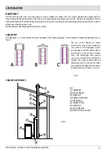
Page 17: ...ses the system s safety CHIMNEYPOT The chimneypot is a crucial element for correct operation of the heating appliance we recommend a windproof chimneypot A see Figure 7 The area of the opening for smoke extraction must be at least double the cross section of the flue piped system and arranged so that the smoke outlet is ensured even in the presence of strong wind The chimneypot must prevent rain s...

Page 18: ...ction rangecookerhood otherstoves etc whichcouldcauseadepressionintheroom Make sure that with all appliances on the pressure drop between the room and the outside does not exceed the value of 4 Pa also for Oyster appliances if the combustion air has not been suitably ducted outside If required increase the intake section of the air inlet which must be made at floor level and always protected with ...

Page 19: ... to or greater than that of the outlet of the appliance Ø 80 mm TYPE OF SYSTEM SMOKE DUCT Maximum length with 1 accessible 90 bend 6 5 metres Maximum length with 3 accessible 90 bends 4 5 metres Maximum number of accessible 90 bends 3 Horizontal sections minimum slope 3 4 metres Use a smoke duct according to the regulations in force in the country of installation and verify that it is compatible w...

Page 20: ...inimum safety distances from combustible materials The previous rules also apply for holes made in walls 2 Oldflue minimumpipeØ100mmwiththeinclusionof an external access door for chimney cleaning 3 External flue made of insulated stainless steel pipes i e with double walls minimum Ø100mm all securely mounted on the wall With windproof chimneypot See fig 7 type A 4 Ducting system using Tee fittings...

Page 21: ...8 93 407 1100 872 407 93 77 114 19 3 DRAWINGS ANDTECHNICAL SPECIFICATIONS Technical Dept All rights reserved Reproduction prohibited DRAWINGS AND CHARACTERISTICS DIMENSIONS OF AKI HYDROMATIC 16 24 M1 STOVE METAL CLADDING ...

Page 22: ...Ø80 Ø50 574 421 374 109 407 1100 1100 904 407 109 77 114 20 3 DRAWINGS ANDTECHNICAL SPECIFICATIONS DIMENSIONS OF AKI HYDROMATIC 16 24 M1 STOVE CERAMIC CLADDING ...

Page 23: ...ze 3 40 mm Pellet hourly consumption Min 1 0 kg h Max 3 5 kg h Autonomy At min 26 h At max 8 h Heatable volume m3 346 40 396 35 462 30 Combustion air inlet Ø 50 mm Smoke outlet Ø 80 mm Air inlet 80 cm2 Rated electrical power EN 60335 1 115W Max 370W Supply voltage and frequency 230Volt 50 Hz Net weight 190 kg Weight with packaging 206 kg Distance from combustible material back side under 20 200 0 ...

Page 24: ...umption Min 1 0 kg h Max 5 3 kg h Autonomy At min 26 h At max 5 h Heatable volume m3 514 40 587 35 685 30 Combustion air inlet Ø 50 mm Smoke outlet Ø 80 mm Air inlet 80 cm2 Rated electrical power EN 60335 1 115W Max 370W Supply voltage and frequency 230Volt 50 Hz Net weight 190 kg Weight with packaging 210 kg Distance from combustible material back side under 20 200 0 mm Distance from combustible ...

Page 25: ... over and handle the majolica parts with care The stoves are delivered in a single package with ceramic panels or steel sides packaged together with the structure and placed on top or at the side Open the package remove the cardboard polystyrene and any straps and position the stove in the preset place making sure that it complies with the requirements The stove body or unit must always be kept in...

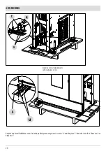
Page 26: ... 24 4 UNPACKING Remove the Suite Club Musa stoves from the pallet by removing the two screws u and the plate s from the stove foot There are four brackets s REMOVING THE FASTENING BRACKETS SUITE CLUB MUSA STOVES ...

Page 27: ...p with the connecting pipe If the stove needs to be connected to an outlet pipe which goes through the rear wall to connect to the flue take utmost care to make sure that the joint is not forced If the stove smoke outlet is forced or used improperly to lift it or position it the operation of the stove can be damagedirreparably 1 TURN THE FEET CLOCKWISE TO LOWER THE STOVE 2 TURN THE FEET ANTICLOCKW...

Page 28: ...ear or top smoke outlet You must purchase the elbow rear outlet or the straight pipe top outlet REAR OUTLET CONNECTION Toinstallthestovewithrearsmokeoutlet inserttheelbow T notsupplied intotheinlet r andpassitthroughthehole f ontheback of the stove Make the necessary connections to the flue ...

Page 29: ...ION To install the stove with top smoke outlet proceed as follows take out the two screws x and remove the piece S remove the knockout hole in the piece S to allow the top smoke outlet remove the two screws y remove the piece W it can be eliminated as it is not needed for the top smoke outlet remove the screw z and the hook S ...

Page 30: ...r T z S 28 5 SMOKE OUTLET CONNECTION insert the linear pipe T not supplied into the inlet r on the stove secure the pipe T to the stove using the hook S and screw z ...

Page 31: ...th the ceramic sides B or metal sides A and prepare them for installation The ceramic sides are already completely assembled ceramicsandmountingbrackets aswellasthemetalsides andmustbefittedaspertheinstructionsonthefollowingpages The claddings are delicate therefore handle with care METAL CLADDING A POS DESCRIPTION No A METAL SIDE 2 M4X12 SCREW 4 M5 NOTCHEDWASHER 4 CERAMIC CLADDING B POS DESCRIPTI...

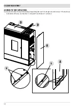
Page 32: ...ASSEMBLY OF SIDE METAL PANEL Youdonotneedtoremovethetoptofitthecladding Simplyliftthepelletcover D fortherightsideorthefrontcover O fortheleftside At the bottom of the stove insert the holes s on the panel A into the hooks v on the stove ...

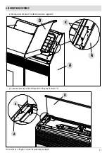
Page 33: ... 31 6 CLADDING ASSEMBLY Technical Dept All rights reserved Reproduction prohibited at the top secure the panel A with the two screws supplied x proceed the same way to fit the left panel A lifting the front cover O ...

Page 34: ...SSEMBLY OF SIDE CERAMIC PANEL Youdonotneedtoremovethetoptofitthecladding Simplyliftthepelletcover D fortherightsideorthefrontcover O fortheleftside At the bottom of the stove insert the holes s on the panel B into the hooks v on the stove ...

Page 35: ... 6 CLADDING ASSEMBLY Technical Dept All rights reserved Reproduction prohibited at the top secure the panel B with the two screws supplied x proceed the same way to fit the left panel B lifting the front cover O ...

Page 36: ...if the distances from the walls allow it otherwise the maintenance can be performed by removing the side of the stove To remove the rear panel remove the four rear screws a and pull panel L away TERMINAL BLOCK ACCESS PANEL To perform the terminal block connections you must remove the right side panel of the ceramic or metal cladding ...

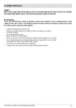
Page 37: ...production prohibited DOOR OPENING To open the decorative door E insert the cold handle Z into the hole in the handle and pull it towards you the same way as you open the firebox door F Attention Onlyopenthedoorswhenthestoveisswitchedoffandcold DECORATIVE DOOR E FIREBOX DOOR F ...

Page 38: ... D 36 7 OPENINGTHE DOORS OPENING FRONT DOOR O To open the door O grip it in the part in front of the stove and lift it up OPENING PELLET DOOR P To open the door D grip it on the side and pull it upwards ...

Page 39: ...chnical Dept All rights reserved Reproduction prohibited OPENING LOWER DOOR Q To open the lower door R first of all you must have opened the decorative door E Then grip the door by the rabbet in the middle and pull it towards you ...

Page 40: ...emittenthatcomeswiththe stoveitself Whenloading donotletthepelletbagcomeintocontactwithhotsurfaces Neverremovetheprotectiongridinsidethehopper No other type of fuel other than pellets is to be inserted into the hopper in compliance with above mentioned specifications Storethesparefuelatanadequatesafedistance Donotpourpelletsdirectlyontothebrazierbutonlyintothehopper Whentheapplianceisrunningandwhe...

Page 41: ...d user Failure to do this may result in unsafe use of the appliance Explanation of the appliance and how it works Necessity to maintain ventilation to the appliance and the issues that may arise otherwise Fuel usage and supply How to light the appliance safely What to do in the event of failed ignitions What to do in the event of alarms in particular those triggered when the appliance runs out of ...

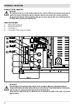
Page 42: ...the event of failed operation if theaforementionedwarningisnotcompliedwith CONNECTION DIAGRAM A1 Heating water supply 3 4 M A2 Heating water return 3 4 M A3 System filling 1 2 A4 System outlet 1 4 M see image on next page IMPORTANT CLEANTHEENTIRESYSTEMBEFORECONNECTINGTHESTOVE INORDERTOREMOVEALLRESIDUEANDDEPOSITS Alwaysinstallshuttersinthesystemleadingtothestovesoastodisconnectitfromthehydraulicsys...

Page 43: ...r standard to the safety discharge to drain the water until the bracket of the hydraulic connections From that point it is MANDATORY to connect a rubber hose that can withstand a temperature of 110 C not supplied and that reaches the outside for any water outlet Themanufactureroftheapplianceisnotliableforanyfloodingcausedbythesafetyvalvesbeingtriggeredifthese havenotbeenjoinedproperlytotheoutsideo...

Page 44: ...henoiseproducedbytheboiler Refertotheinstructionsontheproduct Cleaning should be performed by a qualified technician We also recommend the use of FERNOX CLEANER F3 and LEAK SEALER F4 always available from our authorised distribution centres FERNOX F3 is a neutral product for rapid and efficient cleaning of heating appliances It has been designed to eliminate residues oily depositsandincrustationsf...

Page 45: ...especiallyinthe domesticwaterheatexchanger 25 French Installationofawatersoftener ifwaterhardnessexceeds25 French Fillingthesystemwithtreatedwater demineralised Possiblyprovidingananti condensationcircuit Installation of plumbing bumpers to prevent the phenomenon known as water hammer from occurring alongthefittingsandpipes For those who have very extensive systems with large amounts of water or w...

Page 46: ...othepowersocket Openthiscompartmentbysimplyliftingthecover usingascrewdriver as a lever from inside the power outlet compartment Inside there are two fuses 5x20 mmT delayed 3 15 A 250V which may need to be replaced if the stove is not powered e g the control panel display does not light up operation to be implemented by an authorised and skilled technician ATTENTION Allcleaningand orreplacementofp...

Page 47: ...TRICAL CONNECTION Technical Dept All rights reserved Reproduction prohibited USB SOCKET In case of software update the USB flash drive must be inserted directly in the circuit board pos 25 in circuit board Attention TheUSBsocketmustbeusedbyskilledtechnicians Riskofdamagingtheproduct ...

Page 48: ...REV 2 8902006500 Via La Croce n 8 33074Vigonovo di Fontanafredda PN ITALY Telephone 0434 599599 a s Fax 0434 599598 Internet www mcz it e mail mcz mcz it 11 01 2021 ...

Reviews: