CSP
−
902RFM207E
−
1
ROTORCRAFT FLIGHT MANUAL
MD900 (902 Configuration with PW 207E)
Systems Description
Original
7
−
9
Reissue 2
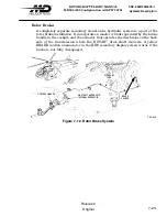
OUTBOARD
ABRASION STRIP
TRIM TAB
ASSEMBLY
MAIN
ROTOR
HUB
PITCHCASE
FLEXBEAM
ROTOR BLADE
INBOARD
ABRASION STRIP
ROTOR BLADE
RETENTION BOLTS
CENTERING
BEARING
PITCH CHANGE
HORN
DRIVE
PLATE
DAMPER
SCISSORS
LOWER
HUB
FLEXBEAM
BUMPER
UPPER
HUB
DRIVE
RING
F92
−
061
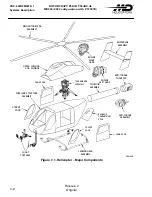
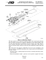
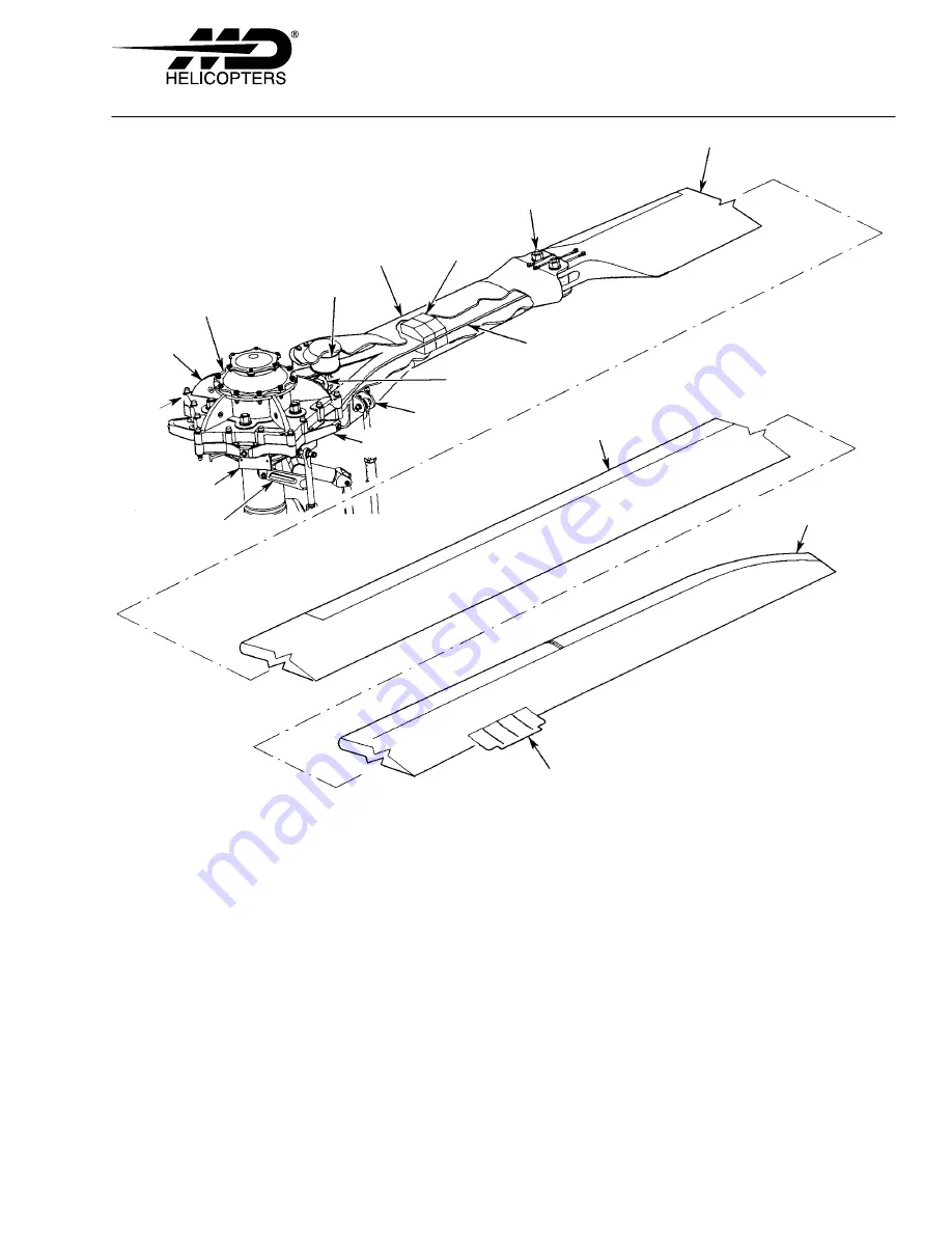
Figure 7
−
4. Main Rotor System
The hub consists of two machined aluminum plates with a steel spacer between
them. The plates are grooved to accept the flexbeams and are bolted together with
the same bolts that attach the flexbeams. The hub mounts to the static mast by
a pair of grease lubricated, tapered roller bearings. A splined drive plate bolts to
the top of the hub and is driven by the main rotor shaft that rotates inside the
mast.
This static mast rotor support configuration has been used successfully in the
OH-6A, AH-64A, and MD500 helicopters and is incorporated into the MD Explorer
for three reasons:
Vibration Control - fuselage/mast/rotor structure is tuned dynamically for mini
mum vibration.
Reduced transmission weight - gearcase is not required to support rotor loads.
Summary of Contents for MD900 Explorer
Page 4: ......

