CSP
−
902RFM207E
−
1
ROTORCRAFT FLIGHT MANUAL
MD900 (902 Configuration with PW 207E)
Systems Description
Original
7
−
31
Reissue 2
7
−
11. FUEL SYSTEM
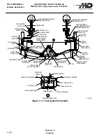
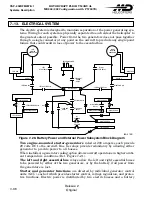
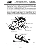
The single crash-resistant elastomeric fuel cell is capable of holding 161.3 U.S.
gallons of jet fuel and is located in the lower fuselage under the main cabin floor
(Ref. Figure 7-17). It is contained between crash-resistant keelbeams and bulk
heads, with a support panel underneath.
The powerplant separation feature includes a partial-height baffle that runs fore
and aft along the bottom center of the cell that provides sufficient fuel reserve for
at least twenty minutes of flight following loss of fuel in the other compartment.
This provides two separate fuel supplies, and each are capable of transferring fuel
from the other. This is a pressurized system with a boost pump and jet pump located
on each side of the longitudinal baffle. With boost pumps operating, fuel is pumped
through jet pumps in the opposite fuel cell cavity. The jet pump draws fuel from
the sump through a pickup and the fuel is ejected on the other side of the longitudinal
baffle.
The fuel system is pressurized having a separate fuel pump located in the sump
in each side of the cell.
The cell is designed with a seven percent expansion space, and has two anti-slosh
baffles across it. Pilot-operated shutoff valves are positioned at the engine firewalls.
Self‐closing breakaway fittings are installed where fuel lines penetrate the cell walls
and where they penetrate the engine deck. Overboard fuel cell vent lines incorporate
rollover valves and flame arrestors located in the vent system stand pipes.
The gravity-type fuel filler port is located on the right side of the fuselage just
aft of the pilot's cockpit door.
Two sump overboard drains for removing sediment and water (one for each side
of the cell) are operated by knobs located under the right side cabin step.
The engine fuel drain system provides a path for residual fuel from the fuel manifold
that remains after shutdown to be returned to the fuel cell.
A provision is made in the fitting at the aft left hand corner of the cell for making
a connection to an optional auxiliary fuel tank.
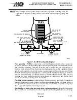
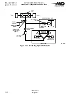
The pilot controls the fuel system by the Fuel System Panel mounted switches.
Fuel level is sensed by a forward probe and an aft probe, and is displayed on the
IIDS. Two fuel pressure switches activate caution lights in the IIDS when the pres
sure falls below the acceptable limit.
Summary of Contents for MD900 Explorer
Page 4: ......

