CSP
−
902RFM207E
−
1
ROTORCRAFT FLIGHT MANUAL
MD900 (902 Configuration with PW 207E)
Systems Description
Original
7
−
33
Reissue 2
NOTE
:
If the voltage for the probe drops below the specified operating limit, the
segments in the fuel quantity vertical scale blank with the digital quantity still
active.
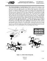
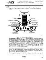
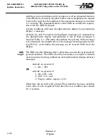
FUEL
FUEL LOW CAUTION
SEGMENTS (YELLOW)
FUEl QUANTITY
SEGMENTS (GREEN)
FUEL LOW WARNING
SEGMENT (RED)
LB
FUEL LOW WARNING TICK MARK (RED)
FUEL FLOW LINE
LOW FUEL PRESSURE
ANNUNCIATORS (YELLOW)
FUEL FILTER IMPENDING
BYPASS ANNUNCIATOR (YELLOW)
FUEL SHUTOFF VALVE POSITION
ANNUNCIATOR (YELLOW)
LOW FUEL PRESSURE
ANNUNCIATORS (YELLOW)
CURRENT FUEL QUANTITY
DIGITAL DISPLAY (WHITE)
FUEL FILTER IMPENDING
BYPASS ANNUNCIATOR (YELLOW)
F92
−
072
Figure 7
−
18. IIDS Fuel System Display
Fuel quantity (FUEL)
is shown by a vertical bargraph inside a fuel tank icon
rectangle,
with the corresponding digit value in pounds, shown immediately below.
The green
bar shortens vertically from the top as fuel is burned proportional to
the total tank
volume. When the green box disappears, two yellow segments illumi
nate below to
indicate a low fuel caution (approximately 45 minute reserve). When
the last yellow
segment disappears, a red segment illuminates below to indicate
low fuel
(approximately 20 minute reserve). Independent left and right fuel low
warning red ``tick'' marks beside the red segments are
activated when the low level
sensor reaches the warning level of 100 lbs.
Fuel flow to the engines
is shown below the fuel
quantity bargraph: Connections
from the fuel tank to each engine is shown immediately
below the digit value of
fuel quantity. A solid line indicates normal fuel flow and
alternating white and yellow
offset segments indicate low fuel pressure.
The display of fuel valve left and right engine position
is shown by a
segment
above and below each fuel line for the respective left and right fuel
valves. During
Summary of Contents for MD900 Explorer
Page 4: ......

