CSP
−
902RFM207E
−
1
ROTORCRAFT FLIGHT MANUAL
MD900 (902 Configuration with PW 207E)
Systems Description
Original
7
−
37
Reissue 2
bus. A starter contactor connects the starter generator to the battery bus. After
a successful start, the starter-generator begins generating current and is brought
on line by the GCU through the generator contactor.
The pilot monitors generator load on the IIDS. The pilot can manually reset or dese
lect either generator by using the generator switches located on the Electrical Master
panel.
A standard 22 ampere-hour nickel-cadmium battery
is used for engine start
and for reserve electric power. A 27 amp hour and 44 amp hour (aft mounted battery
only) are also available as options. The battery relay and external power relay are
controlled by the power switch on the Electrical Master panel. The standard mount
ing of the battery is in the nose of the helicopter, however, an aft-mounted battery
is available as an option.
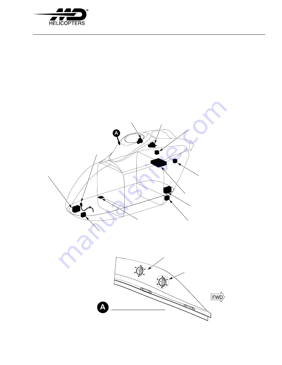
BATTERY
POWER AND L/R
GENERATOR SWITCHES
EXTERNAL POWER BOX RELAY
(FRONT MOUNTED BATTERY)
EXTERNAL POWER
RECEPTACLE
STARTER/GEN
STARTER/GEN
ELECTRICAL
LOAD CENTER
GENERATOR CONTROL UNIT
GENERATOR CONTROL UNIT
F927
−
091a
OPTIONAL REAR-MOUNTED
BATTERY
EXTERNAL POWER BOX RELAY
FOR REAR-MOUNTED BATTERY
VIEW LKG INBD
AIR VENT INLET (REF)
GENERATOR COOLING INLET (IF INSTALLED)
(RH SHOWN; LH OPPOSITE)
GENERATOR COOLING INLET
Figure 7
−
21. Battery Power, External Power, and DC Power Component Locator
Summary of Contents for MD900 Explorer
Page 4: ......

