CSP
−
902RFM207E
−
1
ROTORCRAFT FLIGHT MANUAL
MD900 (902 Configuration with PW 207E)
Performance Data
5
−
54
FAA Approved
Reissue 2
Revision 5
5
−
9.
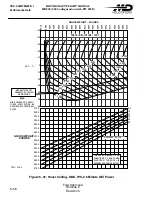
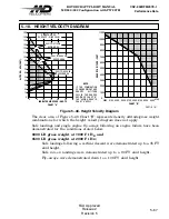
HOVER CEILING, OEI
Description:
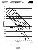
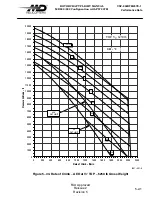
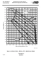
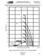
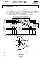
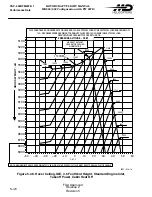
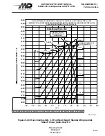
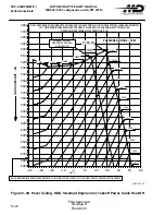
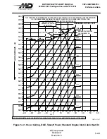
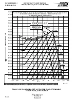
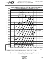
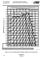
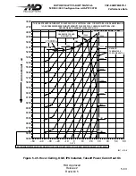
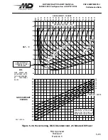
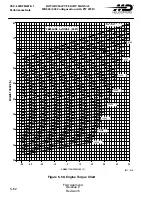
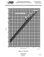
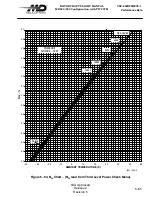
These charts (Ref. Figure 5-46 and Figure 5-47) may be used to deter
mine hover performance in zero wind conditions for internal load operations or
in headwind conditions during external load operations with one engine inoperative
(emergency conditions) and the remaining engine at 2.5 minute power rating.
NOTE
:
Unless otherwise authorized by operating regulations, the pilot is not authorized
to credit more that 50 percent of the performance increase resulting from the
actual favorable head wind increase.
NOTE
:
These charts are not to be used while conducting Category A takeoff and landing
operations.
Use of Chart:
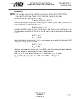
The following example explains the correct use of the chart in
Example 1
: Zero wind
Wanted: Maximum gross weight for hover OGE at 2.5 minute OEI power.
Known: H
P
= 4000 FT, OAT = 10
°
C
Method: Enter the chart at 10
°
C and move right to the 4000 H
P
curve. At this
point move up and read from the gross weight scale, 5275 LB.
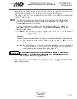
Example 2
: Headwind
NOTE
:
It is essential that reliable wind information be available prior to determining
hover. Additionally, only the lower limit of a gust spread may be used to determine
head wind credit.
Wanted: Maximum gross weight for hover OGE at 2.5 minute OEI power.
Known: H
P
= 4000 FT, OAT = 10
°
C, 10 knot head wind
Method: Enter the chart at 10
°
C and move right to the 4000 H
P
curve. At this
point move down to the 10 knot headwind line. From this point, move to the
left and read from the gross weight scale, 5475 LB.
Next, subtract 5275 LB (from example 1) from 5475 LB to determine the unfac
tored head wind performance increase of 200 LB. However, the pilot is authorized
to allow only 50 percent of the performance credit, resulting in a gross weight
increase to 5375 LB.
Summary of Contents for MD900 Explorer
Page 4: ......

