CSP
−
902RFM207E
−
1
ROTORCRAFT FLIGHT MANUAL
MD900 (902 Configuration with PW 207E)
Systems Description
Original
7
−
3
Reissue 2
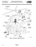
The composite flexbeam main rotor hub replaces the normal hinges with a fiberglass/
epoxy flexbeam that twists and bends to accommodate the blade motions. It, and
the elastomeric lead/lag dampers, are located within the elliptical pitchcase for a
low drag hub that is composed of a minimum number of parts.
The empennage includes a fixed horizontal stabilizer and two controlled vertical
stabilizers that provide directional stability.
The screened NOTAR
inlet is on the top of the cowling, between the engines and
aft of the rotor. In this location it is protected from dust and debris, and is shaped
to direct NOTAR
fan noise up and away from observers on the ground, thus helping
to minimize noise.
The cabin floor is approximately three feet above the ground. This provides space
under the fuselage for the energy absorbing landing gear to deflect, and room in
the lower fuselage for the 161.3 gallon fuel cell. A convenience step is provided
on the right side of the fuselage for entering and departing.
Step/handholds and fold-out work platforms are built into the sides of the fuselage,
forward and aft of the cabin doors, for easy access to equipment located on the
engine and transmission decks.
Two tiedown fittings are positioned high on the sides of the fuselage in line with
the forward edge of the cabin doors, and one on the fuselage centerline just above
the baggage compartment door. Fabric socks are used to capture the blade tips
for tying them to the landing gear crosstubes.
7
−
2.
FUSELAGE
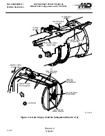
The fuselage contains the cockpit; cabin; baggage compartment; fuel cell; NOTAR
fan, support, and ducts; and avionics equipment. The rotor/transmission support,
engines, and systems equipment are mounted on the top, and the landing gear
on the bottom. The fuselage structure has an aluminum upper deck, main frames,
and anti-plowbeams under the cockpit, with graphite/epoxy skins, keel beams,
cockpit framing, floors, and doors.
The fuselage is one of three components that contribute to an integrated systems
approach to the MD Explorer's hard landing energy absorbing concept. The others
are the landing gear and crew/passenger seats. This approach has served well in
the OH-6A, AH-64A, and MD500 helicopters.
The cabin
has an open flat floor from the front of the copilot's station through
the cabin and to the back of the baggage compartment area. With the seats removed,
the entire floor area is usable for loading cargo.
Space is provided in the nose for the battery; under the cockpit floor and in the
baggage compartment for avionics equipment; and under the baggage compartment
floor for air conditioning equipment. The single fuel cell is mounted in the belly
of the fuselage surrounded by bulkheads fore and aft, and keel beams to the sides.
Summary of Contents for MD900 Explorer
Page 4: ......

