15
5.6 Electrical Installation
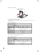
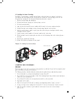
Access for the electrical wires to the terminal module is made via the PG16 cable gland located at the bottom of
the mounting bracket assembly. The cable gland can be removed and replaced with a suitable conduit fitting if
required. The wire routing of a typical installation is shown in the diagram below.
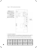
Diagram 10. Typical wire routing
ANALOG OUTPUT
The terminals used are suitable for conductors of 24 to 14 AWG (0.5 to 1.8mm Dia.). The use of 16 AWG
(1.5 mm Dia.) conductors is recommended.
NOTE: When powered by Power over Ethernet (PoE) the 3 on board relays do not require separate 24 VDC
to be energized
If Power over Ethernet (PoE) is used to power the device, then 24 VDC power must not also be connected to the
device, (or conversely if 24 VDC is used to power the MIDAS
®
, then electrical power via the Ethernet port must
not be applied). Failure to observe this requirement may cause damage to the gas detection system and will not
be covered by the standard warranty.
When connecting the wires ensure that the power switch is in the off position.
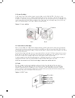
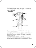
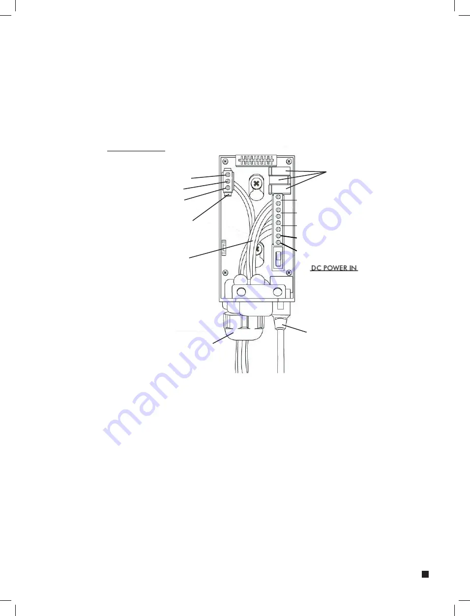
Diagram 11 shows the terminal module layout and terminal identification as well as the jumper locations.
Diagnostic LED lamps are positioned on the internal main chassis for ease of viewing. These indicate that
Ethernet communication activity is active. In some versions of MIDAS
®
the rear mounted Power over Ethernet port
has two LED status lamps; note that these are not utilized and do not illuminate.
24V DC
RELAYS
OUT
COM
EXT INT
ALM 1
ALM 2
F
LT
24V DC IN
0V DC COM
CABLE GLAND
WIRES
RJ45 CONNECTOR


