7
3.1.2 Pump Module
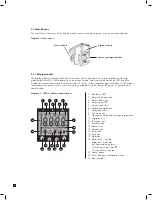
The pump module is located at the back of the main chassis. It draws the gas sample from the inlet port located
at the bottom of the mounting bracket assembly via an inline filter to the sensor cartridge chamber located at
the front of the main chassis. The sample is then exhausted via the exhaust port located at the bottom of the
mounting bracket assembly. The pump and filter assemblies are designed for easy replacement. For replacement
details refer to sections 9.2 and 9.4 respectively.
3.1.3 Sensor Cartridge Chamber
The sensor cartridge chamber is located at the front of the main chassis below the display module. The plug in
sensor cartridge is fitted into this area which makes the electrical connection between the sensor cartridge and
the rest of the electronics as well as providing the chamber where the sensor cartridge is exposed to the sampled
gas. For details of fitting sensor cartridge refer to section 5.9.
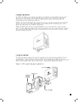
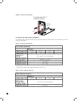
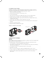
3.2 Mounting Bracket Assembly
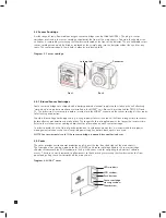
The mounting bracket assembly comprises of the detector mounting bracket, the terminal module, the gas
sample inlet and outlet ports, the cable/conduit entry and Ethernet communications socket.
Diagram 4. Mounting bracket assembly
Mounting bracket
Terminal module
Cable entry
Gas inlet port
Ethernet/PoE socket
Gas outlet port
3.2.1 Mounting Bracket
The metal mounting bracket has two slots that allow the detector to be easily mounted to a wall using two
suitable screw fixings. For further details of mounting the detector refer to section 5.
3.2.2 Terminal Module
The terminal module is located on the mounting bracket. All electrical connections to MIDAS
®
are made via this
module. Wire entry to the terminal module area is via the PG16 cable entry/conduit entry located at the bottom
of the mounting bracket assembly.


