background image

MDF Rose Engine Lathe 2.0 

Build Instructions – Stepper Controls 


22 

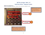
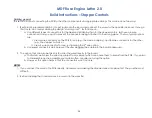
Headers for Integrated Circuits 

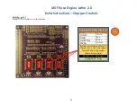
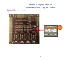
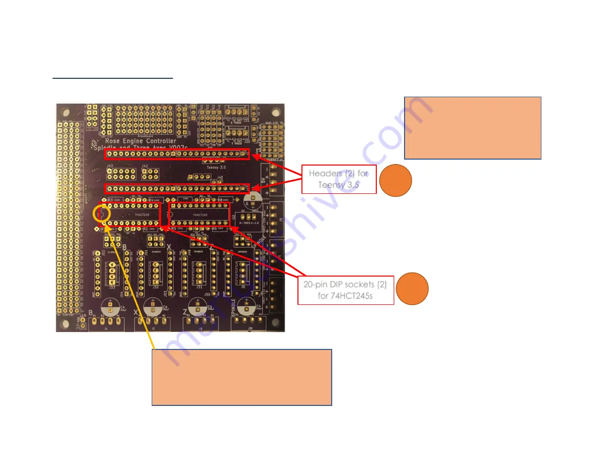
Solder in the 2 headers for the Teensy, and the 2 DIP sockets for the integrated circuits. 


Headers (2) for 

Teensy 3.5 

20-pin DIP sockets (2) 

for 74HCT245s 

103


102


NOTE:

  The headers must be at 90° 

to the circuit board.  It is necessary 

to ensure that they remain 

perpendicular or the Teensy’s pins 

will not fit into the header pin 

holes. 

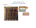
NOTE:

  Both sockets have direction indicators 

on them.  Ensure they match the direction 

indicators on the board (the little curved part 

of the marking on the board).  This is to ensure 

the 74HCT245s are inserted correctly. 

Summary of Contents for Rose Engine Lathe 2.0

Page 1: ...MDF Rose Engine Lathe 2 0 with Stepper Motor Drive Instructions for Building the Stepper Controls Version 1 2 15 December 2020...

Page 2: ...rchase from www ColvinTools com There are some variations from the ideas documented by Jon Magill at www rogueturner com Where this is the case we have tried to document such changes and provide the r...

Page 3: ...1 Assembly of the Control Box Electronics 30 Mounting the Covers 30 Mounting Electronics to the MDF Base 31 Switch Settings 42 Stepper Motor Connections 43 Attaching the Stepper Motor to the Headstock...

Page 4: ...ledge www OTBoK info This document outlines the approach for wiring this machine using 1 Rose Engine Controller Spindle and Three Axes V002c printed circuit board 2 DM542T Stepper Motor Drivers 3 Next...

Page 5: ...em we supply with the MDF Rose Engine Lathe 2 0 Spindle Drive Option includes 1 Everything in the Controls Box the box in blue above a Power cord and on off switch b Power supply c Printed Circuit Boa...

Page 6: ...se Engine Lathe just placing the box somewhere near the lathe 3 This also frees up space under the bed for a Storage of parts or tools or b Making a gap bed lathe 4 The many connections between the va...

Page 7: ...Digi Key ED3054 5 ND 104 10 K resistors 8 Digi Key CF14JT10K0CT ND 105 100 F electrolytic capacitor 1 LCSC C59414 Mfgr p n KM101M050F115A 106 74HCT245 Octal Bus Transceiver 3 state 2 Digi Key 296 1612...

Page 8: ...13 Stepper Motor 1 StepperOnline 23HS30 30045 For the spindle drive NEMA 23 bipolar 1 8 1 9 Nm 2 8A 3 2V 57 x 57 x 76 mm 214 GX 16 4 Plug 1 Amazon May come as a pair of sockets and plugs i e including...

Page 9: ...d head McMaster Carr 90935A137 These work acceptably in the MDF for the purposes they are designed to be used 407 Particle Board Screws 6 3 4 long round head McMaster Carr 91555A115 408 Particle Board...

Page 10: ...ler Mounting bolts nuts and spacers to attach to headstock Mounting screws to attach stepper motor Touch Screen Parts 601 Touch Screen Case 3D printed 1 Colvin Tools Can also get plans to 3D print thi...

Page 11: ...m MDF and 6 4 corner posts made from quarter round trim Removing the top reveals the box shown to the right The quarter rounds are used to give the top and bottom something to set the spacing correctl...

Page 12: ...MDF Rose Engine Lathe 2 0 Build Instructions Stepper Controls 12 Before Assembly The following instructions should be followed before assembling the controls box Bottom This is made from MDF 16 6...

Page 13: ...MDF Rose Engine Lathe 2 0 Build Instructions Stepper Controls 13 Top This is made from MDF 2 4 2 2 4 2 16 3 6 2 2 1 dia typ...

Page 14: ...MDF Rose Engine Lathe 2 0 Build Instructions Stepper Controls 14 Short Sides 2 There are two of these and they are made from MDF 6 6...

Page 15: ...MDF Rose Engine Lathe 2 0 Build Instructions Stepper Controls 15 Long Sides 2 There are two of these and they are made from MDF 16 6...

Page 16: ...F Rose Engine Lathe 2 0 Build Instructions Stepper Controls 16 Quarter Rounds 4 There are four of these and they are made from any good trim material These are radius but that is not terribly critical...

Page 17: ...0 Build Instructions Stepper Controls 17 Assembly Glue the four quarter rounds to the ends of the two long sides Be certain to 1 center the quarter round so there is on each end and 2 ensure the edges...

Page 18: ...th the hole punched out for the cable strain relief Secure the power cable in place using the 3 8 in Twin Screw Cable Clamp Connector Wait until later to tighten the screws holding the power cable int...

Page 19: ...2 0 Build Instructions Stepper Controls 19 Stepper Motor Plugs Use a 2 gang plate which is blank Drill 4 holes which are each 5 8 diameter Label these as Z Axis B Axis X Axis Spindle 1 1 Spindle X Ax...

Page 20: ...options 1 If you want to use an RJ 45 connector to enable disconnecting the display then drill 1 hole which is 31 32 diameter Center it left to right and 1 from the outer edge Label this as o Touch S...

Page 21: ...trols 21 Printed Circuit Board Attach the parts to the Rose Engine Controller Spindle and Three Axes V002C printed circuit board PCB using the instructions below Through Hole Components part 1 Solder...

Page 22: ...DIP sockets 2 for 74HCT245s 103 102 NOTE The headers must be at 90 to the circuit board It is necessary to ensure that they remain perpendicular or the Teensy s pins will not fit into the header pin h...

Page 23: ...h Hole Components part 2 Solder in the components noted below R 78E5 0 1 0 DC DC Converter 100 F Capacitor 107 105 NOTE The DC converter should fit over the box printed for it on the board NOTE Be sur...

Page 24: ...nnector on the PCB for one e g the Nextion display and female connectors for the other e g the stepper motors or ii Use a 5 wire connector for one just ignoring the 5th wire option b Use keyed connect...

Page 25: ...ng part 1 Solder in the cables as noted below Cabling for DM542T Drivers 4 same for B X Z GND White DIR Red STEP PUL Black ENA Yellow Enable is square closest to the J6 J31 J32 J33 label The rest are...

Page 26: ...MDF Rose Engine Lathe 2 0 Build Instructions Stepper Controls 26 Cabling part 2 Solder in the cables as noted below Cabling for 24 VDC Power Feed 24V White 24V Red 22 AWG 2 Cable 15 long 303...

Page 27: ...ange 5V Green 5V is closest to the J20 label The rest are in the order shown in the table Cat 5 or higher If connecting thru the panel to the Nextion HMI display using a cable grip on the panel 7 feet...

Page 28: ...ions Stepper Controls 28 Cabling part 4 Solder in the cables as noted below Jumper for Nextion Power Option JP1 Red or Black 5V 22 AWG 2 Cable is 1 long 303 NOTE If the jumper is not connected there w...

Page 29: ...ted below Cabling for Limit Switches 2 Pin Red GND White or Black 3 3V unused 5V unused Pins 34 to 39 22 AWG 2 Stranded 8 long 303 NOTE it may be easier to attach the jacks to the wires before solderi...

Page 30: ...ics Mounting the Covers The layout below is recommended This minimizes cable management issues when used Spindle X Axis Z Axis B Axis Limit Home Switches 36 34 Touch Screen 35 39 37 38 NOTE Screw thes...

Page 31: ...tepper Controls 31 Mounting Electronics to the MDF Base Mount the electronics to the base piece of the MDF LRS 100 24 DM542T B Axis DM542T X Axis DM542T Z Axis DM542T Spindle Terminal Block PCB sittin...

Page 32: ...installed onto the PCB as shown in the picture to the right The two 74HCT245 integrated circuits are installed as shown in the picture to the right Note that the indicating mark should be on the left...

Page 33: ...wer infeed is connected as Wire Color Power Switch Black Incoming Power Terminal 1 Black Outgoing Power Terminal 2 Wire Color LRS 100 24 Black from Power Switch Terminal 2 L White N Green GND Conducto...

Page 34: ...the V outfeeds is connected up to the terminal block where the power will be distributed 7 V is connected to the other side of the terminal block using a white or black wire That same colour wire is t...

Page 35: ...trols 35 Power Wiring Printed Circuit Board PCB The PCB is connected to the terminal block for power The cable from the PCB is already in place from earlier instructions in this document Terminal Bloc...

Page 36: ...epper Motor Drivers 4 Each of the 4 DM542T stepper motor drivers is connected to the terminal block for power Terminal Block Wire Color DM542T V terminal Red V V terminal White GND Conductor Type Stra...

Page 37: ...20 AWG 4 stranded wire The cable from the PCB is already in place from earlier instructions in this document The cabling for the Spindle s driver is shown the other 3 are similar GND wires tied bonde...

Page 38: ...an RJ 45 connector The cable from the PCB is already in place from earlier instructions in this document PCB Wire Color RJ 45 Pin Rx White Green 1 5V Green 2 Tx White Orange 3 Blue 4 White Blue 5 GND...

Page 39: ...r Audio Jack pin Red Tip pin 2 GND White or Black Sleeve pin 1 NOTES 1 Most audio jacks that are available are stereo with 3 connectors Only 2 are needed so the 3rd one will go unused Typically pins 1...

Page 40: ...PCB is connected to the sleeve on the plug you will be shorting that one to ground and no stepper motor movement will happen Everything will seem to work but the stepper motors won t start running 1...

Page 41: ...Color GX 16 4 Pin A Black 1 A Yellow 2 B Red 3 B White 4 Conductor Type Stranded copper Conductor Size 20 AWG Cable Size 4 conductors cable Cable Length 6 to 8 206 302 1 2 3 4 NOTE When soldering wir...

Page 42: ...2 8A Peak 2 03A RMS 1 ON 2 ON 3 OFF Half Current 4 OFF Pulses Rev 6400 5 OFF 6 ON 7 OFF 8 ON The current could be set higher with this driver however the selected NEMA 23 stepper motor does not need...

Page 43: ...r Wire Cable Wire Color GX 16 4 Pin A Black Black 1 A Green Yellow 2 B Red Red 3 B Blue White 4 Put a long piece of shrink file onto each one of the stepper motor wires before connecting it to the cab...

Page 44: ...a secure way to attach the signal wires to the motor These are available from a number of sources and they can even be 3D printed Look for one online using the term stepper motor back cover In this c...

Page 45: ...building instructions these need to be set based on the alignment of the bracket Attach the spindle pulley to the spindle flange There are 4 screws for this One is indicated here Attach the stepper m...

Page 46: ...to the headstock They need to be tight enough to not slip but don t over tighten them as that will cause the barrel nuts to pull thru the MDF The stepper motor s cable needs to be fed thru the hole in...

Page 47: ...pth of 1 8 Attach one corner of the Nextion HMI using an M3 Thread Forming Screw then center the HMI Drill the other 3 corners and then attach the display using the remaining M3 Thread Forming Screws...

Page 48: ...oints down Insert the Heat Set Inserts There are two options here 1 Using a heat gun insert each of the heat set inserts into the corners of the base These would then be used to attach the top of the...

Page 49: ...ructions Stepper Controls 49 Add Wire Cord Grip The cord grip is used to ensure the signal wire does not pull against the Nextion display Depending on the printing you may need to drill the whole with...

Page 50: ...piece of shrink file onto each one of the Nextion wires before connecting it to the CAT 5 wires Connect the CAT 5 wire to the Nextion wires using a lineman s splice AKA the Western Union splice and s...

Page 51: ...a copy of the Nextion configuration file Download RoseEngine_14 tft and put it in the root folder of a microSD card Notes 1 You can only have one file on this card which is a TFT file The upgrade will...

Page 52: ...y The cable end connected to the Teensy uses a MicroUSB connector The Teensy s jack is noted in the picture to the right Notes Be sure you have a good MicroUSB cable Some are only used for charging a...

Page 53: ...to open it you will get the message as shown here Step 4d Press the button on the Teensy to load the get the Teensy loader This will enable the Teensy loader to recognize which CPU you are using and...

Page 54: ...ss that is a bad translation from Chinese After that message appear remove the microSD card from the Nextion and reboot the Teensy again Step 6 Load the ini file Secure the microSD card which has the...

Page 55: ...ensy column is populated with the same numbers as the Nextion column Repeat for each axis on each page 2 Next verify the Preferences are correct for the Spindle Axes Limits and Returns 3 Select the Ma...

Page 56: ...o use the instructions in the next section to load the programs into all the pieces If it works screw the two pieces together If you took the option to use the heat set inserts back on pg 48 then atta...

Page 57: ...rity_B 1 DistancePer360_B 1 02 RadialOrLineal 0 BRadius 5 Limits Limit Switches Min_Z 34 Max_Z 35 Min_X 36 Max_X 37 Min_B 38 Max_B 39 Returns Return MaxSpeed_Spindle 15011 Accel_Spindle 15012 MaxSpeed...

Page 58: ...Ind IndexId 1 MaxSpeed_Spindle 5070 Accel_Spindle 5071 SpeedPercentage_Spindle 72 Division 0 Degrees 2 Fixed 0 File 1 Index 1 DivisionsOrDegrees_1 2 FixedOrFile_1 0 Size_1 1 875 Index 2 DivisionsOrDe...

Page 59: ...5041 SpeedPercentage_Spindle 42 Z Axis MaxSpeed_Z 5043 Accel_Z 5044 SpeedPercentage_Z 45 X Axis MaxSpeed_X 5046 Accel_X 5047 SpeedPercentage_X 48 B Axis MaxSpeed_B 5048 Accel_B 5049 SpeedPercentage_B...

Page 60: ...ttern_PatternsPer360 8 Pattern_PatternCount 1 Pattern_SegmentLength 1 File page RadialOrAxial_File 0 File_PatternsPer360 7 File_PatternCount 1 File_SegmentLength 1 Segments 2 Actual 3 File_SegmentsOrA...

Page 61: ...ry doable but is not an option we will be providing The components which can be left out when building the system are outlined in the table below Configuration Component Spindle Drive Only Z Axis Z B...

Page 62: ...drivers a This can necessitate the need for different more expensive stepper motors The cost of these different motors can erode the savings for not using the external stepper motor drivers DM542T b I...

Page 63: ...10 Dec 20 Added details for optional configurations Added information for attaching the stepper motor to the headstock 1 0 2 07 Dec 20 Updated p n for item 204 also updated p n qty for item 102 Added...

Page 64: ...eged infringement is permissible under fair use principles in U S copyright laws If you believe material has been used in an unauthorized manner please contact me at ColvinTools Gmail com The layout o...

Reviews: