MDF Rose Engine Lathe 2.0
Build Instructions – Stepper Controls
24
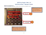
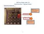
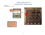
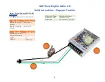
Cabling, general
This section is about connecting the PCB to the other components via appropriate cabling. This can be done two ways:
1.
Best practice recommendation is to put jacks onto the board and connect the wires via the opposite jack end. If you go
that route, do consider making the design “dummy proof”. By that I mean,
a.
Use different types of connectors for the Nextion HMI display than for the stepper motors. Both use a 4-wire
connection, and you want to prevent the connector being attached to the wrong place. The two typical options
are:
i.
Use a male connector on the PCB for one (e.g., the Nextion display), and female connectors for the other
(e.g., the stepper motors), or
ii.
Use a 5-wire connector for one, just ignoring the 5
th
wire option.
b.
Use keyed connectors which prevent the user plugging the cable into the board backwards.
2.
The option that can also be taken is to solder the wires directly to the board.
a.
That works well unless the wires are subject to movement which can cause them to break from the PCB. If you plan
to disassemble and re-assemble your system often, consider not using this option.
b.
However, this option helps in that the connectors won’t jar loose.
NOTES:
1.
If you connect the wires to the PCB directly, I recommend soldering the stranded wires into place first. They are the most
difficult.
2.
Before soldering the stranded wires, be sure to tin the wires first.


