MDF Rose Engine Lathe 2.0
Build Instructions – Stepper Controls
37
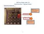
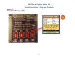
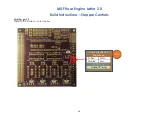
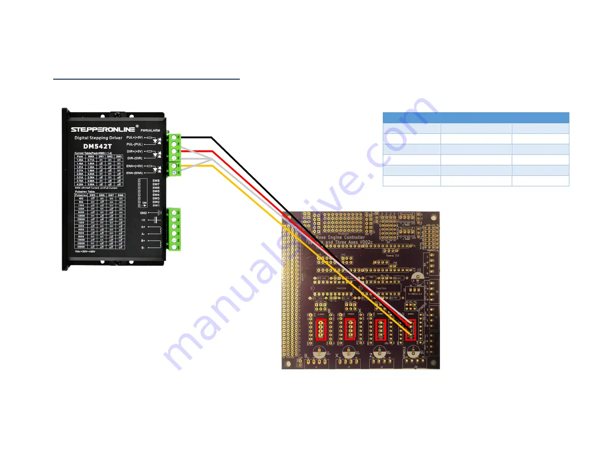
Signal Wiring – PCB to Stepper Motor Drivers (4)
Each of the 4 DM542T stepper motor drivers is connected to the PCB via 20 AWG/4 stranded wire. The cable from the PCB is
already in place from earlier instructions in this document. The cabling for the Spindle’s driver is shown; the other 3 are similar.
* GND wires tied / bonded together.
DM542T
Wire Color
PCB
Dir
Red
¡
DIR
Direction -
White (GND) *
¡
GND
Yellow
¨
ENA
Enable -
White (GND) *
¡
GND
Pulse +
Black
¡
STEP/PUL
Pulse -
White (GND) *
¡
GND
(only one
driver is shown)

