MDF Rose Engine Lathe 2.0
Build Instructions – Stepper Controls
39
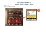
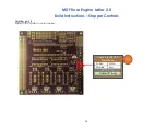
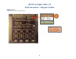
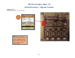
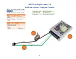
Signal Wiring – PCB to 3.5mm Audio Jack for Limit & Home Switches
The limit switches are connected to the PCB via a 3.5mm (1/8”) audio female jack. Pins 34 - 39 on the Teensy are used (one for
each limit switch). The cable from the PCB is already in place from earlier instructions in this document.
PCB
Wire Color
Audio Jack
¡
pin #
Red
Tip / pin 2
¡
GND
White or Black
Sleeve / pin 1
NOTES:
1.
Most audio jacks that
are available are stereo
with 3 connectors. Only
2 are needed, so the 3
rd
one will go unused.
Typically, pins 1 and 2
should be used, and 3
should be left
unconnected. But
check based on the
jack you are using.
2.
Experience has shown
that it is a good practice
to ensure a mono plug
will work correctly for the
way you have soldered
the connections.
2 -
Tip
1 -
Sle
ev
e
(only one jack
is shown)
207
KEY POINT:
The sleeve must be
connected to ground. (details are
on the next page for this)

