background image


theFan 

TM

 Digital Fan


User Guide, Rev: A/d 

20 / 22


D

ECLARATION OF CONFORMITY


Summary of Contents for theFAN 1.00

Page 1: ... D E IN CAN A D A F A B R IQUÉ AU CA N A D A 10301 avenue Pelletier Montréal Québec Canada H1H 3R2 Tel 514 272 6040 800 663 3020 Fax 514 722 3229 www mdgfog com e mail info mdgfog com User Guide Digital Fan Model 1 00 Revision A d November 2016 MDG Fog Generators Ltd ...

Page 2: ...theFan TM Digital Fan User Guide Rev A d 2 22 Intentionally left blank ...

Page 3: ...Basic Description 6 Working with theFan TM 7 The Keyboard 8 LCD Saver 8 The Menu 9 Operating instructions 11 DMX Control 12 RDM Control 12 Rigging theFan 14 Troubleshooting 15 Technical Datasheet 16 Electrical Requirements 16 Cable Requirements 16 Environmental Requirements 17 Mechanical Data 17 Installation Dimensions 18 Warranty 19 Declaration of conformity 20 Certificate of Compliance 21 Notes ...

Page 4: ...efers so that the users will be aware of any potential danger before performing the task WARNING and CAUTION labels are key equipment parts Do not remove change or cover these labels If the labels are not readable contact MDG Fog Generators Ltd BOLD TEXT Contains important information cautionary steps and warnings that should be read and understood prior to installing the unit BOLD and ITALIC TEXT...

Page 5: ... information for our products Despite it all sometimes a little more is required due to the specifics of your project and installation We re looking forward to go that extra mile for you Contact us By Phone 1 800 663 3020 1 514 272 6040 By Fax 1 514 722 3229 By e mail info mdgfog com On the Web www mdgfog com By Mail MDG Fog Generators Ltd 10301 Avenue Pelletier Montréal QC H1H 3R2 Canada Please n...

Page 6: ...niversal switching power supply 100V 250V 50 60 Hz either sitting on stage or hung from underneath your trussing Omega bracket metric and imperial size clamp sockets Its simple and efficient multi level User Interface accessible from the backlit LCD panel allows for a gradual switch between local mode and most common protocols DMX 512 A USITT and RDM ANSI E1 20 WARNING When not in use ALWAYS switc...

Page 7: ...ol Plug the PowerCON connector 100 250 VAC 50 60 Hz 100 W Block the hand wheels Switch On the power The MDG theFan TM will display during two 2 seconds the following message theFan by MDG V x xx F y yyy where x xx is the version of your theFAN and y yyy is the firmware of the program The program will load the configuration parameters saved in the EEPROM memory These parameters are saved each time ...

Page 8: ...e reaches its maximum value the program continues with the minimum value Mode moves the last selection to the upper level This key has no effect in the first level In a data input menu pressing this key permit to exit the menu without changing any value escape Enter confirms a selection or data value This key has the same effect that the key when scrolling through the menus In a toggle menu this k...

Page 9: ...second Items preceded by the character are state messages or parameters updated by the program The user cannot modify them Items preceded by the character are control parameters The user within specific ranges or choices can MODIFY them In user input mode the value or the choice is preceded with the character This menu can be modified by user This menu cannot be modified by user The value is prese...

Page 10: ... Can be set by RDM Perso 1 CH 2 CH Personality Can be set by RDM Comm Communication toggle The MDG theFan is AUTO controlled by DMX RDM if a signal is present or locally if there is no signal LOCAL controlled by the keyboard ONLY DMX controlled by DMX RDM ONLY Firm x xx Program Firmware DevLab yyyyyy RDM Device Name Can only be set by RDM DevUID yyyyyy RDM Device ID Saver LCD Saver Can be set by R...

Page 11: ... by mode and most of the electronic controls are off Mode 1 Channel Scroll to the Output menu Any value between 0 0 and 26 10 will stop the fan Any value above 26 10 will start the fan The program is written to generate a proportional air flow between 26 10 and 255 100 Mode 2 Channels Scroll to the Fan menu Set the Fan menu to On to start the MDG theFan TM The fan will start to blow immediately Se...

Page 12: ...st DMX channel The MDG theFan has two personalities Mode 1 Channel 1 Fan Off 10 26 Fan Speed from low 10 to high 100 Mode 2 Channels 1 Fan Off 50 128 Fan On 2 Fan Speed from low 0 to high 100 These channels have the same behaviour that the menus of the local interface see Operating instructions paragraph RDM CONTROL The MDG theFanTM can be controlled via a RDM ANSI E1 20 protocol an intelligent bi...

Page 13: ...FO 0x0060 PRODUCT_DETAIL_ID_LIST 0x0070 Air Mover DEVICE_MODEL_DESCRIPTION 0x0080 Atmospheric Other MANUFACTURER_LABEL 0x0081 MDG Fog Generators Ltd DEVICE_LABEL 0x0082 SOFTWARE_VERSION_LABEL 0x00C0 DMX_PERSONALITY 0x00E0 2 DMX_PERSONALITY_DESCRIPTION 0x00E1 theFan x1 Version 1 00 theFan x2 Version 1 00 DMX_START_ADDRESS 0x00F0 1 to 512 SLOT_INFO 0x0120 SLOT_DESCRIPTION 0x0121 DEFAULT_SLOT_VALUE 0...

Page 14: ...eight of the complete fixtures Verify that Cheeseborough bolts are properly tightened Any quarter turn fasteners used omega clamp must be turned a full quarter turn clockwise to lock them Always use a safety cable around one of the handle that can hold at least 10 times the weight of the MDG theFan WARNING The fan is to be installed by qualified installer Installer is responsible for mounting prop...

Page 15: ...y 1 or 2 channels The Output channel must be over 10 for the 1 Channel personality The Fan channel must be ON for the 2 Channels personality Verify the communication mode Comm You cannot control the MDG theFAN locally if you are in DMX mode and vice versa If you are in DMX mode Verify the cable Verify the DMX address Verify the personality Verify the channels LCD displays strange letters or does n...

Page 16: ...paration Da 9 5 0 374 15 0 0 59 Cable Assembly 1 Put bushing and chuck onto the cable 2 Prepare cable as shown above 3 Insert the wire into the terminals and fasten the clamping device by a flat screw driver 4 Push insert and chuck into housing pay attention to the guiding keyway 5 Fasten bushing by means of a fork wrench min Torque 2 5 Nm 1 8 lb ft CABLE REQUIREMENTS Power input 1 mm 18 AWG 3 wir...

Page 17: ...o 50 ºC 32 ºF to 122 ºF operating temperature Dust free space Storage conditions 40 ºC to 60 ºC 40 ºF to 160 ºF 80 relative humidity 60 ºC 140 F MECHANICAL DATA 3 bladed fan 270º tilt Variable speed Max airflow 850 CFM Noise Level 64db full speed Omega clamp socket M12x1 75 metric bolt hole 1 2 x13 imperial bolt hole 2 handles Total net weight 6 8 kg 15 lbs ...

Page 18: ...theFan TM Digital Fan User Guide Rev A d 18 22 INSTALLATION DIMENSIONS ...

Page 19: ...td will repair or replace it free of all charges except transportation costs This warranty applies only to the product itself and MDG Fog Generators Ltd declines responsibility for any losses costs or damages resulting from its use MDG Fog Generators Ltd shall not be liable for consequential damage in case of any failure to meet the conditions of any warranty or shipping schedule nor will claims f...

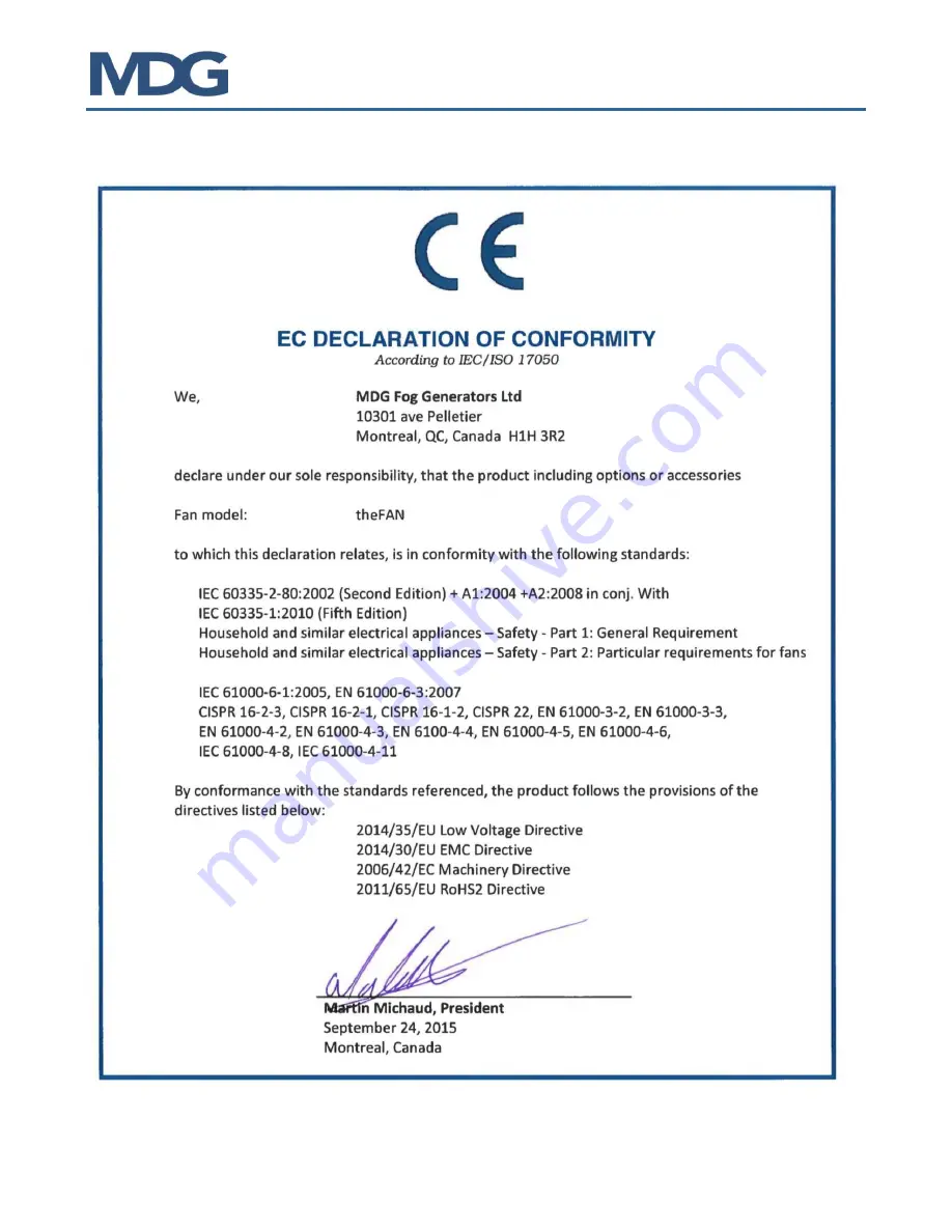
Page 20: ...theFan TM Digital Fan User Guide Rev A d 20 22 DECLARATION OF CONFORMITY ...

Page 21: ...theFan TM Digital Fan User Guide Rev A d 21 22 CERTIFICATE OF COMPLIANCE CSA SPE 1000 for Serial Number below tf 15059 cQPSus certified for Serial Number above tf 15060 ...

Page 22: ...theFan TM Digital Fan User Guide Rev A d 22 22 NOTES ...

Reviews: