© MDM INCORPORATED
WWW.MDMINC.COM
Reliable. Efficient.
PROUDLY MADE
IN THE USA
®
TITAN
P.3
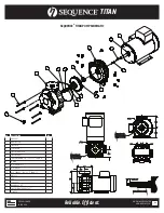
PUMP END ASSEMBLY
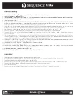
1. Inspect all pump parts (O-ring, O-ring groove, impeller hub ID, motor shaft, etc.) and clean if necessary.
2. Check motor rotation prior to pump assembly.
3. Install threaded rod in end of the motor shaft, leaving .725” ± .005” extended beyond the end of the motor shaft. Use thread locker to secure in place, let cure overnight.
4. Install motor shaft heat shrink tubing sleeve at this time if required.
5. Place slinger over motor shaft.
6. Using a silicon based grease such as Molykote 111
®
, lightly grease the OD of the seal head casing/o-ring and the pump bracket seal bore. Press the seal head
assembly into the pump bracket seal bore to stop by applying pressure only on the seal casing shoulder (do not press on the seal head carbon.), a 1-3/4” socket
has the right clearance to press on the seal casing shoulder. Wipe away any grease squeeze out.
7. Lightly grease the seal seat (mating ring) o-ring and impeller hub ID, press the seal seat into the impeller hub to bottom, making sure the o-ring has not
dislodged and the seal seat sits flat in the bottom of the impeller hub. Wipe away any excess grease. Lightly chamfer the impeller cap recess.
8. Align the bracket over the motor mounting holes and C face. Install bracket/motor mounting bolts and washers. Tighten to 75 in. lbs.
9. Place 3/16” square key in motor shaft keyway. If a motor shaft sleeve is installed, the end of the square key will slide underneath.
10. Clean both seal faces with a lint free tissue and alcohol.
Warning:
Do not use grease on the seal faces. Slide impeller onto motor shaft aligning key and keyways
until seal faces touch.
11. Slide the impeller further towards the motor, compressing the seal and hold in place while placing rubber impeller washer over the threaded rod until it bottoms
in contact with the motor shaft. Impeller metal washer is next placed on top of the rubber impeller washer, lightly grease the side of the metal washer that will
contact with the rubber washer. Lock the impeller in place with the 3/8”-16 hex jam nut, tighten to 50 in. lbs.
12. Lightly grease the impeller cap o-ring gland, place the o-ring in the gland and lightly grease the outside of the o-ring and the impeller nose opening. Assemble
the impeller cap w/ o-ring onto the threaded rod tighten to 50 in. lbs.
13. Place large o-ring into the o-ring gland in the pump bracket, use grease only if required.
14. Assemble volute into position aligning over impeller.
15. Secure volute to bracket using the supplied five 5/16”-18 x 4” through bolts with washers, lock washers and nuts and three 5/16”-18 x 1-1/4” long bolts with
washers and lock washers into the molded inserts. Tighten all bolts to 75 in. lbs.
16. Apply thread sealant to the drain plug threads, tighten to seal.
17. Discharge hardware is supplied as it uses non-standard (and possibly hard to find) nuts.
DISASSEMBLY
1. Shut off power to motor before disconnecting any electrical wiring from the motor.
2. Disassemble volute from bracket by removing the five 5/16”-18 x 4” long hex cap screws, and the three 5/16”-18 x 1.25” hex cap screws.
3. Pump/Bracket/Impeller Assembly may now be pulled back from the Volute.
4. Remove impeller eye ‘cap’ by unscrewing counterclockwise. Remove impeller locknut, unscrew counterclockwise. Slide impeller off of motor shaft.
5. Remove mating ring from impeller. Eye protection is strongly recommended. (If you are replacing the seal)
6. Detach bracket from motor.
7. Remove mechanical seal from bracket by pressing out from the back. Do not dig out from the front. (If you are replacing the seal).


