Chapter 1 General Information
MX-2100/2104
Installation and Operation Manual
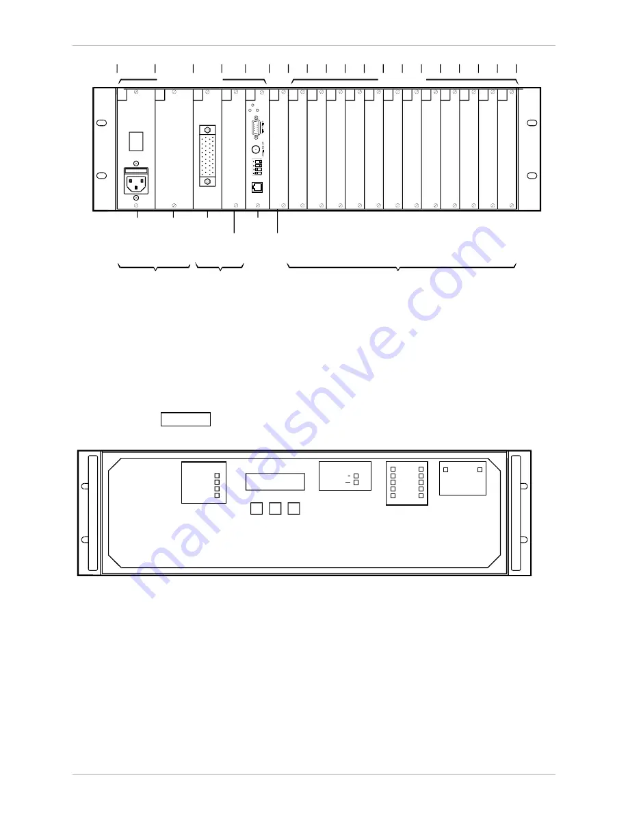
1-8 Physical Description
Slot
1
2
3
4
5
6
7
8
9
10
11
12
13
14
15
16
17
18
System Slots
I/O Slots
1
PS-A
2
PS-B
3
ML-A
KPS
KML.1
4
ML-B
5
CL
6
OP
7
I/O1
8
I/O2
9
I/O3
10
I/O4
11
I/O5
12
I/O6
13
I/O7
14
I/O8
15
I/O9
16
I/O10
17
I/O11
18
I/O12
POWER
Power
Supply
Redundant
Power
Supply
(Optional)
KML
Module
Redundant
KML Module
(Optional)
KCL
Module
Options
Module
Power Supply
Sub-system
Main Link Interface
Sub-system
I/O Modules
as Required
KCL.2
TEST
ALARM
ALM RLY
RESET
Figure 1-4. MX-2100 Enclosure, Rear View
MX-2100 Front Panel
The front panel of the MX-2100 enclosure includes an LCD, three push-buttons,
and labels for the show-through areas for the status indicators located on each
system module. Note that the indicators are arranged in groups (one group for
each system module), that are positioned before the corresponding module slot.
shows the front panel of the MX-2100 enclosure. Refer to the
Operation
chapter for a description of the front panel functions.
TXD
RXD
RTS
M-LEAD
E-LEAD
DCD
DATA
VOICE
CHANNEL
CURSOR
SCROLL
ENTER
ALARM
TEST
SYSTEM
ON LINE
TXD
RXD
LOCAL LOS
REMOTE LOS
B
A
MAIN LINK
B
A
POWER SUPPLY
STATUS
ON LINE
Figure 1-5. MX-2100 Enclosure Front Panel
MX-2104, General Description
The MX-2104 system consists of a 19" 1U enclosure with 4 slots for the installation
of I/O modules. All the modules are inserted through the rear panel. The cable
connections are also made through the rear panel. The front panel includes a
control section with three push-buttons and a two-row LCD display
(16 characters per row), and status and alarm indicators.
The following figure shows a general view of a MX-2104 enclosure.


