Technical
Manual
Temperature
Controller
SCN
‐
RT1
MDT technologies GmbH •
51766 Engelskirchen • Papiermühle 1
Tel.: +49-2263-880 • Fax: +49-2263-4588 • knx@mdt.de • www.mdt.de
9
3
Communication
objects
3.1
Default
settings
of
the
communication
objects
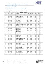
The
following
chart
shows
the
default
settings
for
the
communication
objects:
Default
settings
Nr.
Channel/Input
Function
Length
Priority
C
R
W
T
U
0
Channel
1
Actual
temperature
value*
2
Byte
Low
X
X
X
1
Channel
1
Higher
message
value
1
Bit
Low
X
X
X
2
Channel
1
Lower
message
value
1
Bit
Low
X
X
X
3
Channel
1
Frost
alarm
1
Bit
Low
X
X
X
4
Channel
1
Heat
alarm
1
Bit
Low
X
X
X
5
Channel
1
External
sensor
2
Byte
Low
X
X
6
Channel
1
Setpoint
comfort
2
Byte
Low
X
X
X
X
7
Channel
1
Manual
setpoint
value
offset
2
Byte
Low
X
X
8
Channel
1
Control
value
heating
1
Bit
Low
X
X
X
8
Channel
1
Control
value
heating
1
Byte
Low
X
X
X
8
Channel
1
Control
value
heating/cooling
1
Bit
Low
X
X
X
8
Channel
1
Control
value
heating/cooling
1
Byte
Low
X
X
X
9
Channel
1
Control
value
cooling
1
Bit
Low
X
X
X
9
Channel
1
Control
value
cooling
1
Byte
Low
X
X
X
10
Channel
1
Mode
comfort
1
Bit
Low
X
X
X
11
Channel
1
Mode
night
1
Bit
Low
X
X
X
12
Channel
1
Mode
frost/heat
protection
1
Bit
Low
X
X
X
13
Channel
1
Heating
disable
object
1
Bit
Low
X
X
14
Channel
1
Cooling
disable
object
1
Bit
Low
X
X
15
Channel
1
Heating
request
1
Bit
Low
X
X
X
16
Channel
1
Cooling
request
1
Bit
Low
X
X
X
17
Channel
1
Heating/Cooling
switchover
1
Bit
Low
X
X
18
Channel
1
Max
memory
value
2
Byte
Low
X
X
X
X
19
Channel
1
Min
memory
value
2
Byte
Low
X
X
X
X
20
Channel
1
Min/Max
memory
reset
1
Bit
Low
X
X
X
21
Channel
1
Reset
setpoint
value
1
Bit
Low
X
X
22
Channel
1
DPT_HVAC
Status
1
Byte
Low
X
X
X
23
Channel
1
Error
external
Sensor
1
Bit
Low
X
X
X
24
Channel
1
Actual
setpoint
2
Byte
Low
X
X
X

