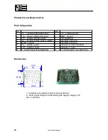
Pin Configuration
Terminal
Designation
Description
1 / 2 / 3 / 4
−
U
S
+U
S
+U
D
−
U
D
bridge supply U
S
Differential input U
D
5 / 6 / 7 / 8
I
A
4...20mA
U
A
±5V
U
M
0..5V
GND output
signal
current
output
signal
voltage
peak value
output
Ground
9/10/11/12
Tare
F1
U
B
F2
tare
sensor 1
DC voltage
supply
sensor 2
13/14/15/16 K1
K1
K2
K2
Relay contacts 1
Relay contacts 2
Note: The ground of the supply voltage
and
the ground of the output signal are connected
to terminal 8.
Adjustment of Input Sensitivity
The input sensitivity can be adapted by displacement of the jumper. The input sensitivity for
position 1 is indicated in the type designation.
Position Input sensitivity in mV/V
Amplification
factor
Output voltage
1
2
3.50
1
5 volts at 2 mV/V
2
1
1.75
2
5 volts at 1 mV/V
10 V at 2 mV/V
3
0.5
0.88
4
5 volts at 0.5 mV/V
10 V at 1 mV/V
4
0.2
0.35
10
5 volts at 0.2 mV/V
10 V at 0.4 mV/V
5
0.5...1.95
0.88...3.33
1.05...4
Instruction Manual
11
Summary of Contents for GSV-1
Page 3: ...Strain Gage Measuring Amplifier GSV 1 Instruction Manual 3...
Page 19: ......


