Page 15
Installation and Assembly
ACC5703
4.3
Pin Assignment
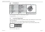
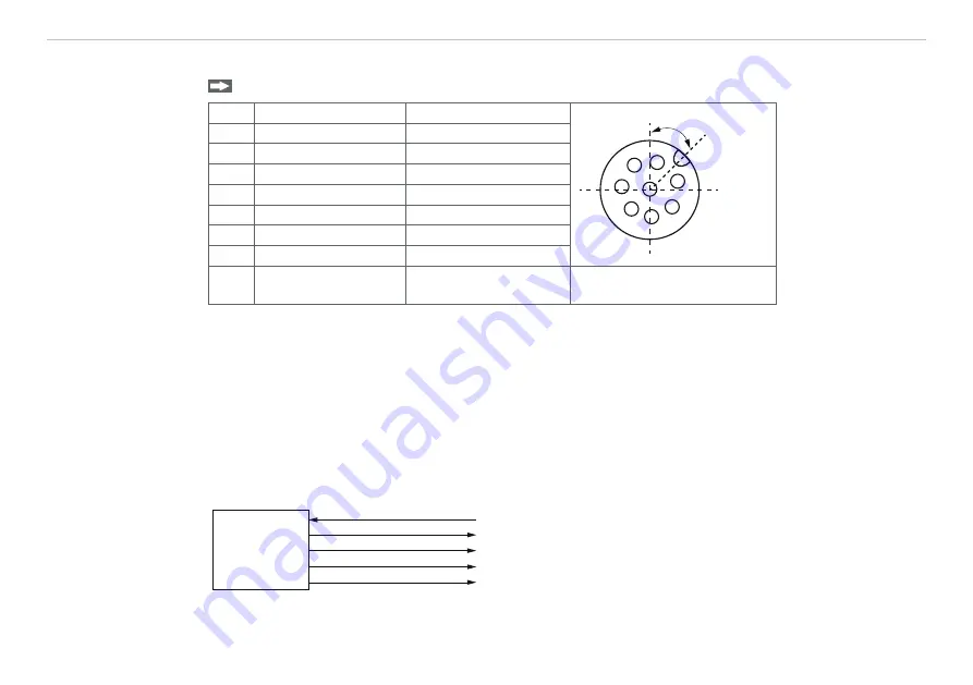
Connect the open cable end in accordance with the color coding
Pin
1
Color
2
Description
2
3
4
8
5
6
7
1
45 °
1
White
Output channel 2
2
Brown
GND (Output)
3
Green
Output channel 3
4
Yellow
RS485+
5
Gray
Output channel 1
6
Black/pink
GND (Supply)
7
Blue
RS485-
8
Red
View of solder pin side, 8-pin,
A-coded, female connector
Fig. 5 Pin assignment of the 8-pin, A-coded, female connector
1) - SA - Connector
2) PCx/8-M12 Power supply and output cable
4.4
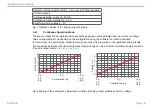
Current and Voltage Output
The sensor makes the acceleration value available as analog output variable either as current or voltage
value on separate pins.
Three output channels can be configured independently with the following settings.
Each output channel can be operated in continuous operation mode or switching operation mode.
Sensor
Versorgungsspannung 5 - 32 V
Analogausgangskanal 1
Analogausgangskanal 2
Digitalausgang RS485
Analogausgangskanal 3
Fig. 6 Current and voltage output


