background image

Summary of Contents for 10" LX100 f/10

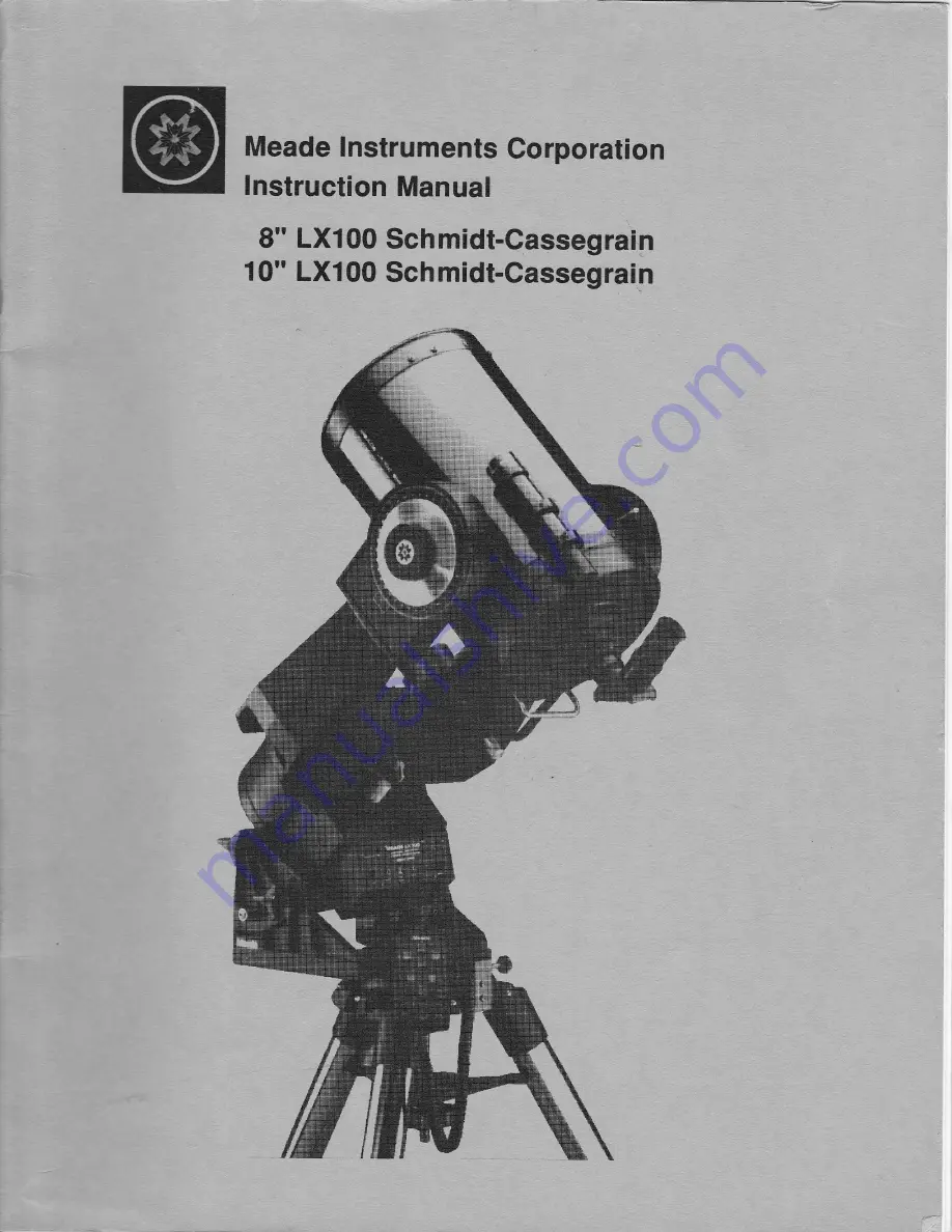
Page 1: ...Meade lnstruments Corporation lnstruction Manual 8 LX100 Schmidt Cassegrain 1 0 LXI00 Schmidt Gassegrain ...

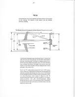
Page 2: ... mirror and results in a focus at the focal plane with light passing through a central perforation in the prirnary mirror The 8 and 10 npdels include oversize 8 25 and 10 375 prinnry mirrors respectively yielding fully illuminated fieldsoFview significantty wider han is possibh with standard size primary mirrors Nob that light ray 2 in the figure would be lostentirely exceptfor the oversize primar...

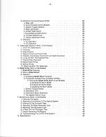
Page 3: ...pe On The Wedge Both 1X100 Models 6 Mounting The Viewfinder a 6 x 30 Viewfinder 8 LX100 1 Attaching the Viewfinder 2 Focusing the Viewfinder 3 Collimating the Viewfinder b B x 50 Viewfinder 10 1X100 1 Attaching the Viewfinder 2 Focusing the Viewfinder 3 Collimating the Viewfinder 7 Attaching the Diagonaland Eyepiece 8 Magnetic Compass Both LXl00 Models a Setting Magnetic Declination b Compass lnst...

Page 4: ... is Smart DrivE 3 Operation 40 a Accessing Smart Drive Functions 40 b Permanent Periodic Error Correction PPEC 41 1 Training the Smart Drive Both 1X100 Models 41 a Building the Worm Model b Erasing the Worm Model c Updating the Worm Model c Electric Focuser Switch d Declination Drift 28 28 28 28 28 28 29 29 29 30 30 30 a1 9t 31 31 32 E 36 37 38 39 40 40 40 42 42 43 43 44 e Declination Motor Direct...

Page 5: ...de a dazzling array of standard equipment features for the serious observer Wide field f 6 3 or classical f 10 opticalsystems mounted atop the largest most rigid fork mounts available a Heavy Duty Fork Mounts The oversized fork mountings included with Meade LX100 s are the largest most rigid mounts ever offered by a commercial Schmidt Cassegrain manufacturer Vibration damping times arthe lowest of...

Page 6: ...l and azimith control variable height field tripod deluxe die cut foam itted carrying case operating instructions b 10 Model LX100 tnctudes 10 Schmidt Cassegrain optical tube assembly specify f 6 3 or f 10 with enhanced multi coatings D 254mm F 1600mm f 6 3 or 2500mm f 10 heavy duty fork mount with 4 dia sealed polar ball bearing 5 75 RA worm gear quartz microprocessor controlled DC servo motor dr...

Page 7: ...g respectively to the Declination and Right Ascension axes in an astronomical observing mode The telescope may of course be used for astronomical observations when set up in the altazimuth mode but the electric motor drive will in this case be non functional from a practical point of view Alternately the field tripod is normally used in conjunction with the appropriate equatorial wedge see section...

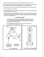
Page 8: ...ar hub at its center 7 Fig 1 To collapse the tripod grasp the tripod head 1 Fig 1 with one hand and with the other hand pull directly up on the central hub of the extension strut system This operation will cause the tripod legs to move inward to a collapsed position PRECAUTIONARY NOTES 1 lf the tripod does not seem to extend or collapse easily do not force the tripod legs in or out By following th...

Page 9: ...pod attached to the wedEe may become seriously imbalanced to the point where the telescope may actually tip over The equatorial wedge for the 8 LX100 telescope is of modern design with several important features incorporated to simplify and facilitate telescope operation After using the wedge you will find that the functional design features included are of very significant value in routine telesc...

Page 10: ...ghten the manual knob Wedge Tripod Head Azimuth Or FFig 4 Azimuth Control 1 Remove the 4 set screws from the wedge and field tripod which plug the attachment holes using a screwdriver 2 Attach the Azimuth Arm to the Equatorial Wedge using the 2 ea 8 32 x 1 2 flat head machine screws 3 Attach the Azimuth Base to the Field Tripod using the 2ea 8 32 x 1 round head machine screws 4 Thread the two Azim...

Page 11: ...y and facilitate telescope operation After using the superwedge for your telescope you will find that the functional design features included are of very significant value in routine telescope operations Some of these f eatures include 1 Attachment of the Superwedge to the field tripod by means o only one manual knob For photographic applications with the ielescope where extreme steadiness is requ...

Page 12: ...ce the Supenaredge on top of the tripod head so that the threaded stud extending from the tripod head passes through the center hole on the wedge floor Make sure the pin extending from the bottom of the azimuth thrust bar is positioned in the slot on the tangent arm see Fig 6 above 4 lnstall the large hand knob compass onto the threaded stud For additional stability pass the three 5 16 1g X 1 114 ...

Page 13: ... plug is included with your hardware package Your focuser is now operational Warning The 10 LXlOO should never be commercially shipped without this red colored head bolt secured in place This is essential during commercial transport where rough handling may occur For your personal transport and storage you will never need to use this bolt again TO COMMERCTALLY RE SHIP THE 10 LXlOO BE SURE TO FOLLO...

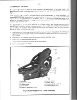
Page 14: ...nation Pointer 5 Optional Declination Motor 6 Declination Slow Motion Control 7 R A Lock 8 R A Slow Motion Control 9 R A Pointer 10 R A Setting Circle 11 LX100 Power Panel 12 Electronic Command Center 13 Diagonal Prism 14 Eyepiece 15 Eyepiece Holder Fig 8 8 LXl00 Telescope ...

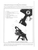
Page 15: ...fisnt Knob Tilt Angle Adj strnent nob Kno i r Altaching ths Telesc pe tc Tilt Plate Drive Base lat far Kneb 4 above Holes lor ACditionai Attachment Knobs B bble Level Manual Knobl0rmpass tor Attachi g the W dge tc Field T pod F g 9 Fla ing the Taleseope on tfte Equatarial Ytledge l hread cne of thes kr b r ecrew a appropriate partially int the hole n the u dersid f tila drive base lccated al the c...

Page 16: ...tilt plate and into the underside of the drive base Tighten down all 3 knobs or screws to a firm feel Extreme force is not necessary in this regard The telescope is now fully mounted onto the wedge and field tripod Adjustments in wedge Iatitude angle and or azimuth orientation may be made with the telescope in place Further details on telescope polar alignment are given below under Lining Up with ...

Page 17: ...focusing need adjustment for your eyes loosen the knurled collar at the objective lens end of the viewfinder 3 Flg 12 enabling rotation of the objective lens cell forward or backward for precise focusing Then tighten down the knurled collar against the objective lens cell to lock the focus in place Note that no focusing is possible or necessary al the eyepiece end of the viewfinder 3 Collimating t...

Page 18: ... factory pre focused at infinity Should this focusing need adjustment for your eyes loosen the knurled collar at the objective lens end of the viewfinder 3 Flg 13 enabling rotation of the objective lens cell 2 Fig 13 forward or backward for precise focusing Then tighten down the knurled collar against the objective lens cell to lock the focus in place Note that no focusing is possible or necessary...

Page 19: ...o the eyepiece holder for straight through observations Note in this case however that the image will appear inverted and reversed left for right With the diagonal prism telescopic images appear correctly oriented up and down but still reversed left or right For terrestrial applications where a fully corrected image orientation is desired both up and down and left for right the optional 924 Erecti...

Page 20: ...netic North which the compass shows and true north where the telescope should be pointed Magnetic Declination should not be confused with the astronomical term Declination which when used with Right Ascension describes the celestialcoordinate system a SETTING MAGNETIC DECLINATION ln order to obtain an accurate reading using the compass you must first adjust for the Magnetic Declination for your lo...

Page 21: ... for 15 degrees west declination which covers Providence Rhode lsland b COMPASS INSTALLATION The Magnetic Compass is now set for the correct declination angle To attach to the Equatorial Wedge follow these steps 1 Snap the Magnetic Compass into the 3 diameter wedge attachment knob after setting the Magnetic Declination as described above Position the compass into the knob so that the 360 degree lo...

Page 22: ...od c FINDING TRUE NORTH The Magnetic Compass is now ready to use Just follow these simple steps for a quick and easy azimuth alignment 1 Loosen the knob compass slightly This allows for rotation of the Equatorial Wedge under the knob compass Fig 16 The magnetic pointing arrow will point to magnetic north Centerline of Wedge Magnetic North Fig 16 Equatorial Wedge ...

Page 23: ...hat the magnetic pointing arrow lies directly over the painted black alignment arrow Fig 17 The North position on the direction scale and the point on the knob compass now point directly north Centerline of Wedge Fig 17 Equatorial Wedge ...

Page 24: ... Fig 18 The centerline of the Equatorial Wedge now falls directly on the true north line Magnetic North True North Centerline of Wedge Fig 18 Equatorial Wedge 4 Tighten the knob compass locking the EquatorialWedge into place The Field Tripod and Equatorial Wedge are now pointed directly toward celestial north without ever having seen the North Star ...

Page 25: ...a battery the telescope operating time will vary depending on the power usage To estimate the operating time of the telescope divide the amp hour rating of the power source by the power usage For example the ammeter reads from 0 to 1000 mA 0 to 1 amps with each illuminated bar measuring 100 mA So if four bars are illuminated the telescope is using 400 mA or 4 amp So the operatinE time of the teles...

Page 26: ...rec y into the Lx10o power panel by using the Electric Focuser jack The Eleclronic Command Center may now be used to control the Electric Focuser to achieve very precise focusing of the telescope g ILLUMI ATED RETTCLE OUTPUT The optional llluminated Beticle can be plu_gggd dkectly into the Lxloo power panet reticte jack eliminating the need for a separate battery box The Reticle Adjust Knob locate...

Page 27: ...ension using the main drive motor The N and S buttons move the telescope in Declination using the optional 39S Dec Motor lf this motor is not aitached these two buttons are non functional The speed at which the telescope moves when using these buttons is determined by the position of the 2Xl32X slide switch see 4 Fig 20 c ELECTRIC FOCUSER BUTTONS Add the optional Meade 1206 Electric Focuser and ul...

Page 28: ... with the 32x West or switch to the 2X speed for final correction QUARTZMANUAL SLIDE SWTCH When the slide switch is on the Quartz position the Quartz crystal in the LX100 Drive is controlling the telescope s tracking speed The E and W buttons override the Quartz crystalto speed up or slow down the tracking speed as long as the button is pressed When the button is released the Quartz crystal resume...

Page 29: ... Check that the Northern Southern N S switch 4 Fig 19 is set for the hemisphere of the observing location and then turn the On Off switch 3 Fig ig1 to 5n hemember The N S switch must be correctly set before the telescope is turned on The po er indicator light 2 Fig 19 should now be lit and the telescope tracking lf the Power Light is not working see Tror Obinootin g tne LX100 Drive System page 49 ...

Page 30: ...t to operate the R A control knob with the telescope fully locked in R A as such operation may result in damage to the internal gear system Releasing the Declination lock 2 Fig 8 permits sweeping the telescope rapidly through wide angles in Declination DO NOT ATTEMPT TO MOVE THE TELESCOPE MANUALLY IN A VERTICAL DIRECTION WHEN THE DECL NATION LOCK IS IN THE LOCKED POSITION To use the Declination fi...

Page 31: ...steady atmospheric seeing the 8 LX100 maybeusedatpowersuptoabout500Xonastronomicalobjects thel0 LXlOOuptoabout600X Generally however lower powers of perhaps 250X to 350X willbe the maximum permissible consistentwith high image resolution When unsteady air conditions prevail as witnessed by rapid twinkling of the stars extremely high power eyepieces result in empty magnification where the object de...

Page 32: ... 50 o 72 63 0 57 Serles 2 Orthoscoplc Eyepleces 4 lements 1 1 4 O D 4mm 45o 6mm 45o 9mm 45o 12 5mm 450 18mm 45o 25mm 45o 320t0140 211tO 210 142 O320 102 O 440 71l0 630 51i0 880 4oo 0 1 10 267 O fio 17 tO 25 128 0 350 89 0 510 64tO 700 500 0 09 333 0 14 222tO 20 160 0 28 111 0 41 80 0 56 625tO O7 417tO 1 t 27BtO 16 200to 8 139 0 32 100 0 45 Super Plossl Eyepleces 5 lernents 1 1 4 O D except as note...

Page 33: ...econds north or south of the celestial equator Thus any point on the celestial equator which passes for example through the constellations Orion Virgo and Aquarius is specified as having 0 0 0 Declination The Declination of the star Polaris located very near the North Celestial Pole is 89 2 The celestial equivalent to Earth longitude is called Right Ascension or R A and is measured in hours minute...

Page 34: ...on as you can see Polaris Finding Polaris is simple Most people recognize the Big Dipper The Big Dipper has two stars that point the way to Polaris see Fig 22 Once Polaris is found it is a straightfonarard procedure to obtain a rough polar alignment To line up the 8 or 10 LX100 with the Pole follow this procedure 1 Using the bubble level located on the floor of the wedge adjust the tripod legs so ...

Page 35: ...recision of polar alignment precise polar alignment requires the use of a crosshair eyepiece The Meade Model 419 MA 12mm llluminated Reticle Eyepiece is weil suited in this application but you will want to increase the effective magnificationthrouglrtheuseofa2Xor3XBarlowlens Thenfollowthisprocedure sometimesbetterknown as the Drift method 1 Obtain a rough polar alignment as described earlier Place...

Page 36: ...power sources into the Power socket of the LX100 Power Panel Slide the On Off switch to the On posilion lmmediately if you put your ear to the drive base of the telescope you will be able to hear the low level noise created by the running motor The drive system turns the fork mount of fte telescope through one complete revolution every 24 hours and results in the stars standing still as you view t...

Page 37: ...n correctly indicate the R A of any object at which the telescope is pointed throughout the duration of the observing session To use the circles to locate a particular object first look up the celestial coordinates R A and Dec of the object in a star atlas Then loosen the R A lock and turn the telescope to read the correct R A of the desired object lock the R A lock onto the object Next turn the t...

Page 38: ...followed for best results in using your telescope 1 Try not to touch the eyepiece while observing Any vibrations resulting from such contact will immediately cause the image to move 2 Allow your eyes to become dark adapted prior to making serious observations Night adaptation generaily requires about 10 to 15 minutes for most people 3 Let the telescope cool down to the outside environmental temper...

Page 39: ... possible greatly increases the odds for a good photograph The Smart Drive makes a quantum leap forward in the elimination of periodic error lt is laught the periodic error due to the worm so that the microprocessor can make the necessary speed correclions usually before the errors are even seen Smart Drive is taught by guiding on a star as if you were taking an astrophotograph This is done by tra...

Page 40: ...when the slide switch 4 Fig 20 is in the Quartz position When in the Manual Mode the telescope will drive at the uncompensated rate determined by the Variable Speed Knob 6 Fig 20 Before Smart Drive can correctly play back the worm model it first needs to know the angular position of the worm The worm has a magnetic index pulse which sends a signal to the Smart Drive every time it reaches the zero ...

Page 41: ... minutes During this time keep the star centered on the crosshairs Note Smart Drive will start beeping 20 seconds before it reaches the index pulse giving you time to get ready When the worm index pulse is reached Smart Drive will give 3 long beeps As you guide on the star Smart Drive will give 1 quick beep every 10 seconds to let you know it is in the train mode When the worm model is complete Sm...

Page 42: ... accidentally hit the focus button while guiding To disable the Electric Focuser buttons 1 Press CTL F 2 Press Near To enable the Electric Focuser buttons 1 Press CTL F 2 Press The following table summarizes the above Control Focus commands Control Focus Commands Smart Drive Feature Buttons Pushed Audible Response Build Worm Model To Exit before Complete CTL F Near 2 Quick Beeps 1 3 Long Beeps Whe...

Page 43: ...oth playback When guiding in Declination if both N and S buttons are pushed the resulting playback will be in one direction only at an averaged speed e Declination Motor Directions When the telescope is first powered up the N Declination button will move the telescope North and the S Declination button will move the telescope South lt is often desirable to reverse these actions especially during t...

Page 44: ...are in cleaning to avoid scratches The aluminized surfaces of the Meade 8 and 10 telescopes willprobably never need re aluminizing if you are careful to replace the dust caps at the eye end and corrector end when the telescope is not in use These dust caps also serve the important purpose of keeping dust and other contaminants off the surfaces of the corrector lens WARNING Do not in any case remov...

Page 45: ...the secondary mirror housing DO NOT FORCETHE 3 COLLIMATION SCREWS PASTTHEIR NORMALTRAVELAND DO NOT ROTATE ANY SCREW oR ScREWS MoRE THAN 2 TURNS IN A COUNTERCLOCKWISE DIRECTION i E NO MORE THAN 2 FULL TURNS IN THE LOOSENING DIRECTION OR ELSE THE SECONDARY MIBROR MAY BECOME LOOSENED FBOM ITS SUPPORT NOTE THAT THE SECONDARY MIBROR coLLIMATIoN ADJUSTMENTS ABE VERY SENSITIVE GENERALLY TURNING A COLLIMA...

Page 46: ...ssues often Avoid using circular motions when wiping and apply only the minimum pressure required to do the job Hard wiping of the correcing plate will introduce fine scratches into the glass lf dewing is a continual problem a Dew Shield see previous description in this manual may be required The Dew Shield effectively re sses the correcting plate from night air and significantly inhibits dew form...

Page 47: ...of either model transmits about 98 of the light impinging at each surface aboul2 of the light impinging each surface is scattered lf a flashlight or other high intensity light source is pointed down the main telescope tube under dark conditions the total amounl of scattered light will be very considerable As a result the optics of the telescope will appear to be of very poor surface quality This s...

Page 48: ...ow battery voltage When the motor is pushed to 32X speeds that is when it has the least amount of torque and requires the most current to move the telescope The 32X centering speed willbe the first indication of low battery voltage and should be taken as a warning especially if the telescope is being operated from your car battery Check the telescope operation using the AC Adapter lf the telescope...

Page 49: ...and South switchable North and South switchable North and South cwit h hlq North and South swltchabh Declinalion Contol System Manual Micrometric landent arm Manual Micronetric tanoent arm Manual Micrornekic tanoent arm Manual Micrometric tanoent arm Motrcr Drive Gear Diameter 5 3i4 Worm Gear 5 3 4 Worm Gear 5 3 4 Worm Gear 5 3 4 Worm Gear M anual Slow Motion Controls Dec and R A Dec and R A Dec a...

Reviews: