background image

– 13 –

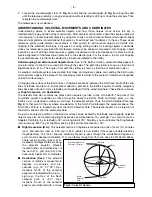
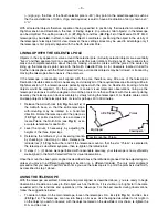
d. Star testing the collimation

With the collimation performed, you will want to test the accuracy of the
alignment on a star. Use the MA 25mm eyepiece and point the telescope at
a moderately bright (second or third magnitude) star, then center the star
image in the telescope’s field-of-view. With the star centered follow the
method below:

Bring the star image slowly out of focus until one or more rings are
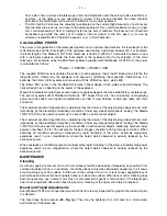
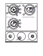
visible around the central disc. If the collimation was performed correctly,
the central star disk and rings will be concentric circles, with a dark spot
dead center within the out-of-focus star disk (this is the shadow of the
secondary mirror), as shown in 

Fig. 12C

. (An improperly aligned

telescope will reveal elongated circles (

Fig. 12A

), with an off-center dark shadow.)

• 

If the out-of-focus star disk appears elongated (

Fig. 12A

), you will need to adjust the primary mirror

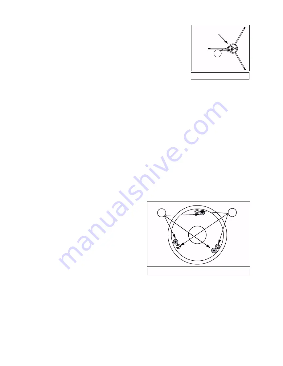
Phillips-head tilt screws of the primary mirror cell (

3, Fig. 8

).

• 

To adjust the primary mirror tilt screws (

3, Fig. 8

), first unscrew several turns the 3 hex-head primary

mirror cell locking screws (

2, Fig. 8

), to allow free turning movement of the tilt knobs.

• 

Using the flexible cable controls (

3, Fig. 1e 

and

4, Fig. 1a

), move the telescope until the star image is

at the edge of the field-of-view in the eyepiece, as in 

Fig. 12B

.

• 

As you make adjustments to the primary mirror tilt screws (

3, Fig. 8

), you will notice that the out-of-

focus star disk image will move across the eyepiece field. Choose one of the 3 primary mirror tilt
screws and slightly move the shadow to the center of the disk. Then slightly move the telescope using
the flexible cable controls to center the star disk image in the center of the eyepiece.

• 

If any further adjustments are necessary, repeat this process as many times as needed until the out-
of-focus star disk appears as in 

Fig. 12C

, when the star disk image is in the center of the eyepiece

field.

• 

With the star testing of the collimation complete, tighten the 3 hex-head primary mirror locking screws
(

2, Fig. 8

).

2

Fig. 7:

Diagonal Assembly.

3

2

Fig. 8:

Primary Mirror Cell.

1

Remove
adhesive
backing

Summary of Contents for 114ST EQ-D

Page 1: ...INSTRUCTION MANUAL Meade 114ST EQ D 4 5 Equatorial Reflecting Telescope Meade Instruments Corporation ...

Page 2: ...ot included in this warranty but are covered under separate warranties issued by Meade International Distributors RGA Number Required Prior to the return of any product or part a Return Goods Authorization RGA number must be obtained by writing to MIC or calling 949 451 1450 Each returned part or product must include a written statement detailing the nature of the claimed defect as well as the own...

Page 3: ...and Coordinates 8 Lining Up with the Celestial Pole 9 Using the Telescope 9 Using Setting Circles 10 Calculating Power 11 Maintenance 11 Cleaning 11 Mount and Tripod Adjustments 11 Collimation 12 a Correct Collimation 12 b Diagonal Holder Adjustments 12 c Primary Mirror Adjustments 12 d Star Testing the Collimation 13 Specifications Model 114ST EQ D 15 Optional Accessories 15 ...

Page 4: ... mounting bolts 17 Focuser drawtube and eyepiece holder 18 Eyepiece holder thumbscrew 19 Focuser 20 Viewfinder bracket 21 Focus knobs 22 R A lock 23 Dec lock 24 5 x 24 viewfinder 25 Viewfinder focuser 26 Viewfinder adjustment thumbscrews 27 R A setting circle 28 Dec setting circle 29 Latitude dial 30 Azimuth lock 31 Declination axis 32 Tripod leg brace 33 Tripod leg brace support 34 Tripod legs 35...

Page 5: ...ay assembly Fig 1c Mount features Fig 1f Leg brace and tray assembly Fig 1g Attaching tripod leg to mount Fig 1e More mount features Fig 1d Optical tube attachment underside view Fig 1a Model 114ST EQ D Optical tube assembly 5 31 23 23 28 22 13 37 36 32 33 35 15 14 29 27 10 34 14 30 3 11 38 ...

Page 6: ... tripod legs evenly apart so that the accessory tray can be positioned to attach to the 3 leg braces 3 Use the provided 3 short screws washers and bolts to attach the accessory tray 36 Fig 1f to the tripod Line up one of the leg braces 32 Fig 1f between the opening of one of the tripod leg brace supports 33 Fig 1f on the tripod so that one of the short screws will be able to pass through the holes...

Page 7: ...in telescope The 5 x 24 Viewfinder 24 Fig 1a and viewfinder bracket 20 Fig 1a attaches to the telescope tube assembly as described above In order for the viewfinder to be functional however it must be aligned to the main telescope so that both the viewfinder and main telescope point at the same position in the sky With this simple alignment performed finding objects is greatly facilitated since yo...

Page 8: ...tude and longitude grid for the celestial sphere These lines are known as Right Ascension and Declination The celestial map also contains two poles and an equator just like a map of the Earth The poles of this coordinate system are defined as those two points where the Earth s North and South poles i e the Earth s axis if extended to infinity would cross the celestial sphere Thus the North Celesti...

Page 9: ...racy the telescope can track accurately by slowly turning the telescope s R A flexible cable control and keep objects in the telescopic field of view for perhaps 20 to 30 minutes 1 Release the Azimuth lock 30 Fig 1a and 1e of the Azimuth base so that the entire telescope with mounting may be rotated in a horizontal direction Rotate the telescope until the polar axis 10 Fig 1c points due North Use ...

Page 10: ...r blurred or distorted due to temperature differences between inside and outside air Also it is a good idea to allow your telescope a chance to reach the ambient surrounding outside temperature before starting an observing session Avoid viewing objects low on the horizon objects will appear better resolved with far greater contrast when viewed higher in the sky Also if images appear to shimmer in ...

Page 11: ...er but does affect such optical characteristics as field of view flatness of field eye relief and color correction The maximum practical magnification is determined by the nature of the object being observed and most importantly by the prevailing atmospheric conditions Under very steady atmospheric seeing the Meade 114ST EQ D may be used at powers up to about 228x on astronomical objects The maxim...

Page 12: ...Fig 10 the 3 Phillips head diagonal tilt screws 1 Fig 7 Note To adjust these screws you must first remove an adhesive backing must be unthreaded slightly to the point of where you can tilt the diagonal holder 3 Fig 7 from side to side by grasping the diagonal holder with your hand and tilt until you see the primary mirror become as centered in the reflection of the diagonal mirror as possible Once...

Page 13: ... To adjust the primary mirror tilt screws 3 Fig 8 first unscrew several turns the 3 hex head primary mirror cell locking screws 2 Fig 8 to allow free turning movement of the tilt knobs Using the flexible cable controls 3 Fig 1e and 4 Fig 1a move the telescope until the star image is at the edge of the field of view in the eyepiece as in Fig 12B As you make adjustments to the primary mirror tilt sc...

Page 14: ... 14 Fig 12 Collimation A B C 4 5 3 3 1 2 2 2 2 1 3 4 1 Fig 11 Primary Mirror Misalignment Fig 9 Correct Collimation Fig 10 Diagonal Mirror Misalignment ...

Page 15: ...opes that accommodate 1 25 eyepieces Meade 3 element Modified Achromatic eyepieces available in focal lengths of 9 and 40mm provide a high level of image resolution and color correction at an economical price Also at slightly higher prices Meade 4 element Series 3000 Plössl eyepieces yield wider fields of view with excellent edge of field corrections and are available in a range of focal lengths i...

Page 16: ...R O D U C T S D I V I S I O N Meade Instruments Corporation World s Leading Manufacturer of Astronomical Telescopes for the Serious Amateur 6001 Oak Canyon Irvine California 92618 949 451 1450 FAX 949 451 1460 www meade com 2003 ...

Reviews: