background image

12

Looking at or near the 

Sun

will cause 

irreversable

damage to your eye. Do not point this telescope at or near the

Sun. Do not look through the telescope as it is moving.

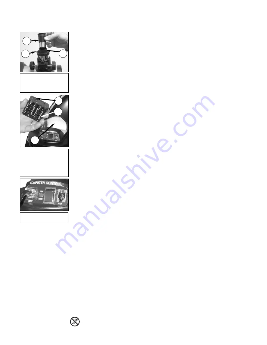
Remove the battery holder from the compartment and carefully lift the 9v connector out
from the compartment. Take care not to accidentally detach the wires of the battery con-
nector from the base. Whenever you replace the batteries, to safeguard the wires, discon-
nect the 9v connector from the battery holder before removing the batteries.

Insert eight AA-size batteries into the battery holder, oriented as shown on the diagram on
the battery slots of the battery holder. Connect the 9v connector plug to the battery holder.
Carefully replace the battery holder back into the battery compartment. Replace the cover.

CAUTION:

Use care to install batteries as indicated by the battery compartment.

Follow battery manufacturer's precautions. Do not install batteries backwards or
mix new and used batteries. Do not mix battery types. If these precautions are not
followed, batteries may explode, catch fire, or leak. Improperly installed batteries
void your Meade warranty. Always remove the batteries if they are not to be used
for a long period of time.

14.

Connect Autostar:

Be certain that the power switch on the computer control panel  is in

the OFF position. Plug the coil cord of the Autostar Controller into the HBX port 

. Turn on

the power switch; the red LED lights when power is supplied to the panel. See 

Fig. 12.

NOTE:

The Autostar handbox does not require batteries; the telescope’s batteries

supply power to Autostar.

15.

Remove the dust cover:

Pull out the dust cove

r

(

12, Fig. 1

) from the optical tube assem-

bly (

13, Fig. 1

).

Assembly of the basic telescope is now complete.

The Red Dot Viewfinder

Because the main telescope has a fairly narrow field of view, locating objects directly in the
main telescope can sometimes be difficult. The red dot viewfinder (

Fig. 13)

projects a small red

dot that permits you to more easily locate objects. When the red dot viewfinder and optical tube
are aligned to each other, both point to the same position in the sky. An object located in the
viewfinder is therefore in the eyepiece of the main telescope. 

Aligning the Red Dot Viewfinder:

It is recommended that you perform steps 1 through 4 of this procedure during the daytime and
step 5 at night.

1.

Loosen the tripod base lock knob (

26, Fig. 1

) and the Altitude lock (

10, Fig. 1

), so that the

telescope can move freely. 

2.

If you have not already done so, place a low-power (

e.g., 25mm) eyepiece in the diagonal

prism of the main telescope (

3, Fig. 1)

and point the telescope at an easy-to-find land

object (

e.g., the top of a telephone pole or sign). Turn the focuser knob (

1, Fig. 1

) to focus

the image in the eyepiece. Center the object precisely. 

3.

Re-tighten the tripod base lock knob (

26, Fig. 1

) and  the Altitude lock (

10, Fig. 1

) so that the

telescope does not move during the procedure.

4.

Rotate the intensity knob to turn the red dot viewfinder On (rotate the knob to change the
intensity of the red dot; see 

Fig. 13

). Looking through the viewfinder. Turn the viewfinder’s

two alignment screws (

8, Fig. 1

) until the viewfinder’s red dot points precisely at the same

object as centered in the eyepiece. The red dot  viewfinder is now aligned to the main 
telescope. 

5.  Check this alignment on a celestial object, such as the Moon or a bright star, and make

any necessary refinements.

Fig. 11: Insert eight AA-size
batteries inside the battery
compartment:
(1) Battery compartment 
(2) Battery holder
(3) 9v connector 

1

2

3

Fig. 12: Connect Autostar to
the HBX port.

Fig. 10: Insert the eyepiece
(1) into the eyepiece holder
(2), tighten eyepiece thumb-
screw (3) (Reflector models).

3

2

1

Summary of Contents for DS-2000 Series

Page 1: ...Instruction Manual DS 2000 Series Altazimuth Maksutov Cassegrain Telescopes MEADE COM...

Page 2: ...on of the image In the refracting telescope light is collected by a 2 element objective lens and brought to a focus at F In contrast the reflecting telescope uses a concave mirror for this purpose F E...

Page 3: ...ing Satellites 36 Appendix D Training the Drive 37 Appendix E Battery Replacement 38 Appendix F How to Manually Set the Time and Date 38 Appendix G Electronic Controller DS 2000EC Users Only 39 Option...

Page 4: ...the optical tube Place the base of the optical tube A over the slot on the mounting plate B Thread the two lock knobs C through the slot on the mounting plate and into the screw holes in the base of t...

Page 5: ...ry holder back into the battery compartment Replace the cover 7 Connect Autostar Be certain that the power switch J on the computer control panel is in the OFF position Plug the coil cord of the Autos...

Page 6: ...e Lock Knob 17 Battery Compartment 18 Azimuth Setting Circle 19 Tripod Legs 20 Inner Support Struts 21 Mounting Lock Knobs 22 Accessory Tray 23 Accessory Tray Attachment Bolts 24 Tripod Legs Locks 25...

Page 7: ...the manual vertical movement of the telescope Turning the Altitude lock counterclockwise unlocks the telescope enabling it to be freely tilted by hand on the vertical axis Turning the Altitude lock c...

Page 8: ...11 for more information Note It is not necessary to remove the tray each time you collapse the tripod The tray is designed to be collapsed with the legs 2 Tripod Legs Locks 3 Lift the lock up to loos...

Page 9: ...Sync feature is accessed by mistake press MODE to return to the previous screen See HIGH PRECISION page 27 for more details about this feature MODE Key Returns to the previous menu or level The MODE...

Page 10: ...Allows you to scroll through menu options The menu is displayed on the top line of the screen and the options within the menu are displayed one at a time on the second line Press and hold a Scroll key...

Page 11: ...firm feel only do not overtighten While observing you may wish to loosen this knob and rotate the mounting arm assembly and optical tube on the horizontal axis 5 Attach the Mounting Plate If your tel...

Page 12: ...e Red Dot Viewfinder Because the main telescope has a fairly narrow field of view locating objects directly in the main telescope can sometimes be difficult The red dot viewfinder Fig 13 projects a sm...

Page 13: ...er called a Barlow lens Consisting of a lens mounted in a 4 long 10cm tube the Barlow doubles or triples the power obtained when an eyepiece is used alone In the example above a 25mm eyepiece results...

Page 14: ...If the image is fuzzy or ill defined reduce to a lower power eyepiece where the heat waves do not have such an effect on image quality Observing in early morning hours before the ground has built up i...

Page 15: ...he view No shadows are seen during a full Moon causing the overly bright surface to appear flat and rather uninteresting Consider the use of a neutral density Moon filter when observing the Moon Not o...

Page 16: ...ge 27 1 Tighten Locks Tighten the Altitude lock 10 Fig 1 and tripod base lock knob 26 Fig 1 2 Plug in Autostar Make sure the telescope power switch is in the OFF position Plug Autostar into the HBX po...

Page 17: ...e Autostar s Arrow keys to center the star in the eyepiece 10 To Start Tracking Once the star is centered press ENTER to select Astronomical The telescope s tracking motors then engage It may take the...

Page 18: ...sed on the date time and location entered The alignment stars may change from night to night All that is required is for the observer to center the selected stars in the eyepiece when prompted NOTE Th...

Page 19: ...rocedure as described below remains the same just choose a different object in step 3 1 After the telescope is aligned Select Item Object displays Press ENTER 2 Object Solar System displays Press ENTE...

Page 20: ...level press MODE to return to the topmost level Select Item Object Autostar Navigation Exercise To demonstrate how the Autostar menu structure works the following exercise calculates Sunset time so a...

Page 21: ...mbers and Text into Autostar To enter numbers and text Use the Up and Down Arrow keys to scroll through numbers 0 9 and the alphabet The Down Arrow key begins with the letter A the Up Arrow key begins...

Page 22: ...ing objects such as the International Space Station the Hubble Space Telescope Global Positioning System GPS satellites and geosynchronous orbit satellites User Objects allows the user to define and s...

Page 23: ...g a new date into the Setup Date menu See DATE page 25 Moonrise and Moonset calculates the time that the Moon rises or sets on the current date Find rise and set times for other dates by entering a ne...

Page 24: ...N and OFF When ON is dis played press ENTER to activate the alarm When the alarm time arrives Autostar beeps Press ENTER to deacti vate the alarm Eyepiece Calc calculates information about an eyepiece...

Page 25: ...that date See EVENT MENU page 23 Time changes the time entered into Autostar Setting the correct time is critical for Autostar to properly calculate locations and events Time may be set to 24 hour mo...

Page 26: ...uilding is obstructing the telescope For example you might begin to track the satellite at 15 altitude instead of 5 See OBSERVING SATELLITES page 36 for more information about satellites Calibrate Mot...

Page 27: ...s moving DS 2000 TIPS Surf the Web One of the most exciting resources for astrono my is the Internet The Internet is full of web sites with new images discoveries and the lat est astronomical informat...

Page 28: ...ecting Prism The 90 diagonal provided with DS 2000 Series refractors results in upright but reversed viewing of land subjects The 928 45 Erecting Prism 1 25 orients the image correctly in terrestrial...

Page 29: ...nd electronic circuitry Collimation DS 2000 refracting telescopes are optically aligned collimated at the factory prior to shipment and it is never necessary to re collimate the optics of these models...

Page 30: ...cause irreversable damage to your eye Do not point this telescope at or near the Sun Do not look through the telescope as it is moving 2 1 3 3 2 1 2 3 4 5 1 2 1 2 3 2 1 2 3 4 3 6 2 5 1 4 Fig 23 Fig 24...

Page 31: ...irror tilt screws are located behind the primary mirror at the lower end of the main tube See Fig 25 Before adjusting the primary mirror tilt screws first unscrew by several turns use either a hex wre...

Page 32: ...c speed f 13 8 Near focus approx 11 5 ft 3 5m Resolving power 1 3 arc secs Multi coated optics standard Limiting visual stellar magnitude approx 11 7 Image scale 1 16 inch Maximum practical visual pow...

Page 33: ...r or right angle 8 x 21mm Telescope mounting Single arm motorized Alt Az Battery user supplied 8 x AA Accessories Bubble level compass Instruction Manual 494 Autostar Processor 68HC11 8MHz Flash Memor...

Page 34: ...nd its Declination 50 Right Ascension R A This celestial version of longitude is measured in units of hours hr minutes min and seconds sec on a 24 hour clock similar to how Earth s time zones are dete...

Page 35: ...row keys to enter the digits for the Declination coordinate of your object If necessary use the Scroll Keys to change to When you are finished press ENTER 8 Autostar then prompts you to enter the size...

Page 36: ...g tree or hill press ENTER and Autostar starts to move the telescope along the expected satellite track When the track clears the obstruction press ENTER again to pause the telescope then continue wit...

Page 37: ...gives only the briefest introduction to astron omy If you are interested in pursuing further studies a few topics are suggested below that are worth reading up on Try looking up some of these topics i...

Page 38: ...w key to move to the next position 8 JAN is now highlighted Press the Scroll Up key until MAR displays Press the Right Arrow key to move to the next position 9 2 is now highlighted The date display no...

Page 39: ...y to change the speed at which the telescope slews to an object Each press of the SPEED key changes the slew speed to the next slower setting If the controller is already on the slowest slew speed lig...

Page 40: ...y on the Electronic Controller and the telescope slews momentarily in the vertical and horizontal directions to test the motors 8 When the test is complete light 1 remains on lights 2 3 and 4 turn off...

Page 41: ...r s Glossary feature The Glossary menu provides an alpha betical listing of definitions and descriptions of common astronomical terms Access directly through the Glossary menu or through hypertext wor...

Page 42: ...her side Fig 36 In 1610 Galileo the first person to observe Saturn through a telescope did not understand that what he was seeing were rings Instead he believed that Saturn had ears Saturn s rings are...

Page 43: ......

Page 44: ...Goods Authorization RGA number must be obtained from Meade by writing or calling 800 626 3233 Each returned part or product must include a written statement detailing the nature of the claimed defect...

Reviews: