GETTING STARTED
1.Parts Listing
In keeping with the ETX philosophy of elegant simplicity, the ETX is virtually completely assembled at the Meade
factory; getting the telescope ready for first observations requires only a few minutes. When first opening the
packing box, note carefully the following parts included with the ETX Astro Telescope:
•
The ETX Astro Telescope with fork mount system.
•
8 x 21mm Viewfinder, packed in a separate, small box.
•
Super Plössl (SP) 26mm eyepiece, packed in plastic storage container.
•
Table Tripod legs (3 pcs), packed in a plastic bag.
•
Hex-wrench set with 3 (English-format) wrenches, packed with the manual.
•
The 8 x 21mm Viewfinder is packed separately from the main telescope in shipment to avoid the possibility
of the viewfinder slipping in its bracket and scratching the viewfinder tube.
2. Assembly Instructions
For assembly, have at your access a Phillips-head screwdriver and three AA-size batteries. Basic assembly of the
telescope requires only a few steps:
NOTE. The viewfinder should be checked for correct focus prior to installation in the viewfinder bracket. See
telescope use, point 5a, below.
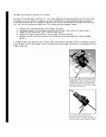
a. Slide the viewfinder into its bracket (5, Fig. 2) with the rubber-eyecup-end of the viewfinder fitting first
through the front end of the bracket. It may be necessary to slightly unthread the six alignment screws (4
and 6, Fig. 2) to fit the viewfinder into the bracket. With the viewfinder inside the bracket, tighten (to a firm
feel only) the six alignment screws down against the viewfinder tube. Alignment of the viewfinder is detailed
in this manual.
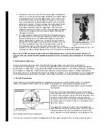
b. Remove the SP 26mm eyepiece (1, Fig. 1) from its plastic
storage container and place it in the telescope's eyepiece holder
(4, Fig. 1) tightening the eyepiece- holder's thumbscrew to a firm
feel only.
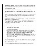
c. With the telescope lying on your lap or on the floor, use a
Phillips-head screwdriver to remove the three screws (1, Fig. 3)
that attach the metal base plate (5, Fig. 3) to the bottom of the
drive base (6, Fig. 3). Thread the center tripod leg (the leg with
the latitude scale) in to the central hole (3, Fig. 3) of the metal
base plate. Then, using the tripod leg to hold the base plate,
carefully pull the base plate from the drive base.
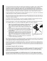
d. Insert three AA-size batteries in the battery clips located inside
the drive base (be careful to avoid touching the thin wires
leading from the battery mounting board to the motor). Orient the
batteries as shown on the battery mounting board (Fig. 4). Then
re-attach the metal base plate to the bottom of the drive base using the three screws (1, Fig. 3). Unthread
the center tripod leg. Basic assembly of the ETX is now complete.
Fig. 2: The Viewfinder. (1) Lens Cell; (2)
Knurled Lock- Ring; (3) Viewfinder; (4)
Front Alignment Screws; (5) Viewfinder
Bracket; (6) Rear Alignment Screws.
Summary of Contents for ETX Series
Page 20: ......


