background image

13

reflecting telescopes because of the “fast” f/4.5 to 
f/5 focal ratio of the primary mirror.

In typical Newtonian reflectors with more 
conventional focal ratios (i.e. longer focal ratios), 
when the observer looks down the focuser tube 
(without an eyepiece in the focuser), the images 
of the secondary mirror, primary mirror, focuser 
tube and the observer’s eye appear concentric 
relative to each other. This is how the collimation 
was adjusted in the section for the Simplified 
Collimation described above.

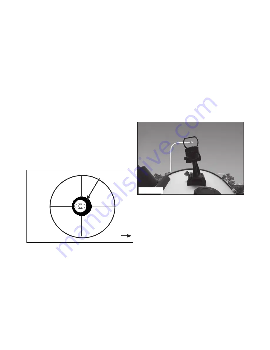
However, with the short focal ratio primary mirror 
of the LightBridge Plus, true collimation requires 
that the secondary mirror be offset in 2 directions: 
(1) away from the focuser and (2) towards the 
primary mirror, in equal amounts. This offset is 
approximately 1/8” in each direction. Note that 
these offsets have been performed at the factory 
prior to shipment of your telescope. It is only 
necessary for you to confirm that the telescope 
has not been badly jarred out of collimation, and to 
perform the final fine-tuning on an actual star under 
the night sky. See Figure 30.

Figure 30

ALIGNING THE RED-DOT FINDER
It is recommended that you perform steps 1 and 2 
of this procedure during the daytime and step 3 at 
night. 

1. If you have not already done so, place the low-
power 26mm) eyepiece in the focuser draw tube. 
(26, Fig. 2) and point the telescope at an easy-to-
find land object (e.g., the top of a telephone pole). 
Turn the focuser knob (23, Fig. 2) so that the image 
is sharply focused. Center the object precisely 
in the main telescope’s field of view and keep it 
centered during the finders alignment procedure. 

2. Rotate the dial on top of the finder to change 
the intensity until you are comfortable with the 
brightness. Push the lever below the finder to 
change the shape of the red dot with four different 
indicator shapes: a dot, a cross, a diamond and a 
bullseye.  

To align the finder, adjust the hex screws on the top 
and side of the finder with the supplied hex wrench 
until the finder’s red dot points precisely at the same 
object as centered in the main telescope. The red 
dot finder is now aligned to the main telescope. 
 
3. Check this alignment on a celestial object, 
such as the Moon or a bright star, and make any 
necessary refinements.

Figure 31

USING THE DOBSONIAN TELESCOPE
1. Your Dobsonian has been designed with some 
inherent friction. You want the telescope to move 
easily when you position it, but you also want it 
to stay in the position you place it. Using any kind 
of oil, silicone spray, wax, or grease will ruin the 
performance by causing the telescope to move too 
easily. Just keep the altitude and azimuth bearing 
surfaces clean; that’s all the maintenance required.

2. The altitude bearing surfaces (10, Fig 1) of the 
telescope may become dirty with use. If they do, 
clean these bearing surfaces with a dry cloth or 
paper towel. Do not use solvents or alcohol-based 
cleaning solutions as this may damage the bearings 
or the painted surfaces of the telescope.

3. You will notice that your telescope will move 
in altitude by raising and lowering the tube, and 
in azimuth by rotating the base. As you observe 
objects in the night sky they will appear to drift out 
of the field of view due to the Earth’s rotation. To 

Toward 
primary 
mirror

Secondary 
mirror offset

Summary of Contents for LightBridge Plus

Page 1: ...Instruction Manual LightBridge Plus Truss Tube Dobsonian Telescopes...

Page 2: ...eversible damage to your eye Eye damage is often painless so there is no warning to the observer that damage has occurred until it is too late Do not point the telescope at or near the Sun Do not look...

Page 3: ...l system 10 Simplified collimation 10 Enhanced collimation 12 Aligning the red dot finder 13 Using the Dobsonian telescope 13 Calculating magnification 14 Observing 14 Some tips 17 Care of the optics...

Page 4: ...cage 10 Altitude bearing 2 11 Primary mirror cover 12 Side base panels 2 13 Front base panel 14 Rear base panel 15 Base panel thumbscrews 12 16 Base bottom panels 2 17 Integrated carry handles 18 Eye...

Page 5: ...s without springs 38 Fan 39 Fan power connector FIGURE 2 FOCUSER ASSEMBLY 23 Coarse focus knob 24 Fine focus knob 25 Tension knob 26 Focuser draw tube 27 2 to 1 25 eyepiece adapter 28 Eyepiece lock th...

Page 6: ...using The correct orientation of the top panel is with the six threaded holes facing up See Figure 4 Step 4 To secure the azimuth bearing system in place On the adjustment knob bolt 34 place one small...

Page 7: ...ct tray orientation is with the screws placed under the tray and out of view Note It is not recommended to install the altitude brake 19 until the optical tube lower cage 9 is placed onto the base ASS...

Page 8: ...w and brake parts provided The altitude brake can be adjusted as needed to induce additional friction on the altitude motion Note When using heavy eyepieces or accessories the optical tube balance poi...

Page 9: ...position under the heavy accessory weight Experiment with these knobs to discover which adjustments are comfortable with your viewing style Step 7 Lift to remove the dust cover from the primary mirror...

Page 10: ...er collimator to help you to collimate your telescope see Optional Accessories Before your first observing session take the time now to familiarize yourself with the following collimation procedure so...

Page 11: ...lder 1 2 Correct 1 and incorrect 2 collimation as viewed by a star test Figure 24 1 2 3 4 5 1 2 1 1 2 2 3 3 4 Figure 25 Figure 26 Figure 27 Figure 28 4 3 2 5 1 6 1 Parabolic Primary Mirror 2 Secondary...

Page 12: ...can be seen centered within the secondary mirror s reflection With the secondary mirror thus aligned the image through the draw tube appears as in Fig 28 4 Primary mirror adjustments If the secondary...

Page 13: ...ield of view and keep it centered during the finders alignment procedure 2 Rotate the dial on top of the finder to change the intensity until you are comfortable with the brightness Push the lever bel...

Page 14: ...al Length ___________________ Eyepiece Focal Length Example Using the 26mm eyepiece supplied with the 10 f 5 LightBridge Plus telescope the power is Power 1270mm ______ 49x approx 26mm The type of eye...

Page 15: ...planets that you can easily observe in your telescope Venus Mars Jupiter and Saturn Nine planets travel in a fairly circular pattern around our Sun Any system of planets orbiting one or more stars is...

Page 16: ...housands of stars with your telescope At first you may think stars are just pinpoints of light and aren t very interesting But look again There is much information that is revealed in stars The first...

Page 17: ...es vertically and or horizontally as needed At higher powers astronomical objects will seem to move through the field of view of the eyepiece more rapidly Place the object to be viewed at the edge of...

Page 18: ...g lens causes virtually no degradation of image quality and should not be considered reason to clean the lens B When absolutely necessary dust on the mirror should be blown off with an ear syringe ava...

Page 19: ...Eyepiece Primary Mirror Parabolic BK7 mirror Diffraction limited Secondary Mirror Support 4 vane steel Base Assembly No tool needed assembly 4 sided structure Altitude Bearings 110mm diameter Azimuth...

Page 20: ...e Eyepiece Primary Mirror Parabolic BK7 mirror Diffraction limited Secondary Mirror Support 4 vane steel Base Assembly No tool needed assembly 4 sided structure Altitude Bearings 130mm diameter Azimut...

Page 21: ...e Eyepiece Primary Mirror Parabolic BK7 mirror Diffraction limited Secondary Mirror Support 4 vane steel Base Assembly No tool needed assembly 4 sided structure Altitude Bearings 170mm diameter Azimut...

Page 22: ...tion that you want but also give you the eye relief you need Other qualities to look for with eyepieces are the apparent field size which is how large an object looks in an eyepiece and coatings which...

Page 23: ...ctors use a parabolic figured mirror which corrects for spherical aberration inherent in other more standard reflector types that use a spherical mirror The secondary mirror is a flat optical surface...

Page 24: ...o Meade freight prepaid with proof of purchase This warranty applies to the original purchaser only and is non transferable Meade products purchased outside North America are not included in this warr...

Page 25: ...25 DRAWING OF IMAGE photocopy this page OBSERVER OBJECT NAME DATE TIME OBSERVED CONSTELLATION EYEPIECE SIZE SEEING CONDITIONS EXCELLENT GOOD POOR NOTES OBSERVATION LOG...

Page 26: ...26 DRAWING OF IMAGE photocopy this page OBSERVER OBJECT NAME DATE TIME OBSERVED CONSTELLATION EYEPIECE SIZE SEEING CONDITIONS EXCELLENT GOOD POOR NOTES OBSERVATION LOG...

Page 27: ...27 DRAWING OF IMAGE photocopy this page OBSERVER OBJECT NAME DATE TIME OBSERVED CONSTELLATION EYEPIECE SIZE SEEING CONDITIONS EXCELLENT GOOD POOR NOTES OBSERVATION LOG...

Page 28: ...14 2725 00 Sept 2018 REV 0 We appreciate your business Keep in touch Let s get social meadeinstruments meadeinstruments meadeinstrument Share your photos with us MeadeMoments Social meade com For spec...

Reviews: