background image

11

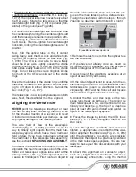
1. Firmly hold the counterweight shaft secure so 
it cannot swing freely. Loosen the R.A. lock(Fig. 
1, #17). The optical tube now moves freely about 
the R.A. axis. Rotate the telescope so that the 
counterweight shaft (Fig. 1, #9) is parallel (hori-
zontal) to the ground(see Fig. #26).

2. Unlock the counterweight lock knob and slide 
the counterweight along the counterweight shaft 
until the telescope remains in one position with-
out tending to drift down in either direction about 
the RA axis. Then re-tighten the counterweight 
lock knob, locking the counterweight securely in 
position.

Now, hold the optical tube so that it cannot 


swing freely. Lock the R.A. lock and while hold-
ing the OTA in place, unlock the Dec. lock (Fig. 
1, #18). The OTA is now able to move freely 
about the Dec. axis. Lightly loosen the cradle 
ring lock knobs (Fig. 2 - 4, #27) so that the main 
tube slides easily back and forth in the cradle 
rings. Do not loosen the cradle ring lock knobs 
too much or the OTA can slip out of the cradle 
rings.

Move the main tube in the cradle rings until the 
telescope remains in one position without tend-
ing to drift down in either direction. Re-lock the 
Dec. lock (Fig. 2 - 4, #27).

The telescope is now properly balanced on both 
axes. Next, the viewfinder must be aligned.

Aligning the Viewfinder

NEVER

 point the telescope directly at or near 

the Sun at any time! Observing the Sun, even 
for the smallest fraction of a second, will result 
in instant and irreversible eye damage, as well 
as physical damage to the telescope itself.

The wide field of view of the telescope’s 
viewfinder(Fig. 2 - 4, #33) provides an easier 
way to initially sight objects than the main tele-
scope’s eyepiece, which has a much narrower 
field of view. If you have not already attached 
the viewfinder to the telescope tube assembly, 
see the section 

UNPACKING AND ASSEMBLY

.

In order for the viewfinder to be useful, it must be 
aligned to the main telescope, so both the view-
finder and telescope’s optical tube point at the 
same position in the sky. This alignment makes 
it easier to find objects: First locate an object in 

the wide-field viewfinder, then look into the eye-
piece of the main telescope for a detailed view.
To align the viewfinder, perform steps 1 through 
7 during the daytime; perform step 8 at night.

1. Remove the dust covers from the optical tube 
and the viewfinder.

2. If you have not already done so, insert the 
low-power 26mm eyepiece into the eyepiece 
holder or diagonal of the main telescope.

3. Look through the viewfinder eyepiece at an 
object at least 200 yards away. 

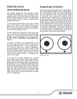
4. If the distant object is not in focus, turn the fo-
cus lock ring on the front of the viewfinder coun-
terclockwise to loosen the viewfinder front lens 
cell(see Fig. 28). Twist the front cell until focus is 
achieved and retighten the focus lock ring.

5. Unlock the R.A. and Dec locks so the tele-
scope turns freely on both axes. Then point the 
main telescope at a tall, well defined and sta-
tionary land object (e.g., the top of a telephone 
pole) at least 200 yards distant and center the 
object in the telescope’s eyepiece.

6. Focus the image by turning the OTA focus 
knobs (Fig. 2 - 4, #29). Retighten the R.A. and 
Dec. locks.

7. Look through the viewfinder and loosen or 
tighten, as appropriate, one or both of the view-
finder alignment thumbscrews (Fig. 2 - 4, #35) 
until the viewfinder’s crosshairs are precisely 
centered on the object you previously centered 
in the main telescope’s eyepiece. You are now 
ready to make your first observations with your 
telescope! 

8. Check this alignment on a celestial object, 
such as a bright star or the Moon, and make 
any necessary refinements, using the method 

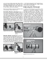
Figure 28: 

Viewfinder adjustments

Focus Lock ring

Focus Lock ring

Front Lens Cell

Front Lens Cell

Alignment 

Alignment 

screws

screws

Summary of Contents for LX70 Series

Page 1: ...1 Instruction Manual LX70 Series German Equatorial Telescopes...

Page 2: ...observer that damage has occurred until it is too late Do not point the telescope at or near the Sun Children should always have adult supervision while observing The name Meade and the Meade logo ar...

Page 3: ...ving by Moving the Telescope Manually 12 Observe the Moon 13 Tracking Objects 13 Locating the Celestial Pole 14 General Maintenance 15 Inspecting the Optics 15 Collimating the Newtonian Reflector 16 O...

Page 4: ...ing Circle not shown RA Setting Circle Locking Knob RA Clutch Locking Knob see inset DEC Clutch Locking Knob DEC Slow Motion Control Knob RA Slow Motion Control Knob Polar Scope Front Cap Polar Scope...

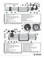
Page 5: ...26 34 41 42 26 25 27 28 29 30 31 32 33 34 34 35 36 37 42 46 45 48 47 47 Figure 3 LX70 Reflector Optical Tube Front Dust Cover not shown Dovetail Rail Cradle Ring Cradle Ring Lock Knobs 1 4 20 Accessor...

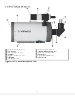
Page 6: ...der Viewfinder Dust Caps Viewfinder Adjustment Screws Viewfinder Bracket with Lock Knob Optical Tube Assembly OTA Diagonal Mirror Diagonal Mirror Thumbscrews Extension Tube Figure 4 LX70 Maksutov Opti...

Page 7: ...ding the inner legs un til the tripod head is approximately level to the ground Relock the leg lock knob until firm 3 Attach the spreader bar to the tripod Thread the small end of the Mount Locking Kn...

Page 8: ...the other When the pointer points at your latitude tighten both screws until they make contact with the mount At your observing site set up the tele scope assembly so that the tripod leg below the co...

Page 9: ...OTA you will need to balance the telescope before use See the section BALANCING THE TELE SCOPE 11 Assemble the viewfinder Locate the view finder bracket Carefully remove the rubber O ring from the br...

Page 10: ...the holder and tighten the thumbscrews to a firm feel only Insert the supplied eyepiece Fig 4 31 into the diagonal mirror Tighten the eye piece holder thumbscrews Fig 4 32 to a firm feel to secure th...

Page 11: ...sembly see the section UNPACKING AND ASSEMBLY In order for the viewfinder to be useful it must be aligned to the main telescope so both the view finder and telescope s optical tube point at the same p...

Page 12: ...nning observer is to overpower a telescope by using high magnifications which the telescope s aperture and atmospheric con ditions cannot reasonably support Keep in mind that a smaller but bright and...

Page 13: ...stars appear to move from East to West The speed at which the stars move is called the si dereal rate You can track objects at this rate by using the RA and DEC slow motion control cables Fig 1 19 an...

Page 14: ...here you align the mount to the southern celestial pole To do this it is necessary to reference star patterns since the southern celestial pole has no nearby bright stars The closest bright star to th...

Page 15: ...to the optics d If the LX70 is used outdoors on a humid night water condensation on the telescope sur faces will probably result While such conden sation does not normally cause any damage to the tel...

Page 16: ...ly unthreaded to the point where the secondary mirror holder Fig 35 3 can rotate about its axis parallel to the main tube Grasp the sec ondary mirror holder avoid touching the mir ror surface with you...

Page 17: ...17 Figure 34 Figure 36 Figure 37 Figure 38 Figure 39 Figure 40 1 2 3 4 5 1 2 3 2 3 1 2 3 4 5 1 2 3 4 Figure 35 6 2 1 2 1 2 3 Newtonian Reflector section view Newtonian Reflector section view...

Page 18: ...native to the 140 may also be employed with any LX70 Se ries telescope 905 Variable Polarizer 1 25 The 905 sys tem includes 2 Polarizer filters mounted in a spe cially machined cell for glare reductio...

Page 19: ...termined by longitude lines The zero line was arbitrarily chosen to pass through the con stellation Pegasus a sort of cosmic Green wich meridian R A coordinates range from 0hr 0min 0sec to 23hr 59min...

Page 20: ...ircle ring until the objects DEC coordinate is aligned with the 0 registration mark If the procedure has been fol lowed carefully the bright star should now be in the center of the telescope eyepiece...

Page 21: ...homa City Oklahoma 35 N Ottawa Ontario 45 N Philadelphia Pennsylvania 40 N Phoenix Arizona 33 N Portland Oregon 46 N Salt Lake City Utah 41 N San Antonio Texas 29 N San Diego California 33 N San Franc...

Page 22: ...80 000km from Earth and is best ob served during its crescent or half phase when Sunlight strikes the Moon s surface at an angle It casts shadows and adds a sense of depth to the view No shadows are s...

Page 23: ...us objects that are self illu minated by nuclear fusion in their core Because of their vast distances from our solar system all stars appear as pinpoints of light irrespective of the size of the teles...

Page 24: ...ve provided the defective part is returned to Meade freight prepaid with proof of purchase This warranty applies to the original purchaser only and is non transferable Meade products purchased outside...

Page 25: ...25 OBSERVATION LOG...

Page 26: ...26 26 OBSERVATION LOG...

Page 27: ...27 OBSERVATION LOG...

Page 28: ...28 28 2014 Meade Instruments Corp reserves the right to change product specifications or to discontinue products without notice 12 2014 LX70 SERIES 14 9287 00 Rev 0...

Reviews: