12
only) prevents the telescope from being moved manually, but engages the verti-
cal motor drive for AutoStar II operation.
1*
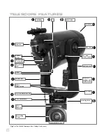
Dust Cover:
Gently pry the dust cover from the front lens of the telescope.
Note:
The dust cover should be replaced after each observing session and the
power turned off to the telescope.
1(
Optical Tube:
The main optical component that gathers the light from distant
objects and brings this light to a focus for examination through the eyepiece. The
tube contains the primary mirror which floats on a layer of adhesive that results
in zero-stress to the glass and no distortion to the optics.
2)
Fan:
AutoStar controls the fan operation. The amount of time required to stabi-
lize the temperature will be dependent upon ambient conditions including the
observation site and preexisting condition of the telescope. The fan should be
activated at the beginning of the observation session to accelerate the tempera-
ture stabilization. As soon as the optics have reached an equilibrium with the
environment the fan should be turned off. Fan operation time should range
between 5 and 25 minutes. While it is permissible to run the fan continuously it is
not recommended because the very slight vibration of the fan may cause notice-
able movement of the objects observed in the sensitive optics.
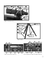
The Viewfinder
2!
8 x 50mm Viewfinder:
A low-power, wide-field sighting scope with crosshairs
that enables easy centering of objects in the telescope eyepiece.
2@
Viewfinder Objective Lens:
Gathers the light for the viewfinder.
2#
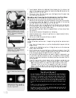
Viewfinder Locking Ring:
Locks the objective lens into place. Unlock to adjust
the focus of the objective lens. See page 18 for details.
2$
Viewfinder Adjustment Screws:
Use these six screws to adjust the alignment
of the viewfinder.
2%
Viewfinder Eyepiece/Focuser:
The eyepiece magnifies the image collected by
the viewfinder’s objective lens. Rotate the eyepiece to focus.
2^
Viewfinder Bracket and Mounting:
Holds the viewfinder in place.
The Tripod
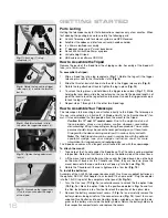
2&
Tripod Base with leg receptacles:
Attach the mounting base (see
1@
) to the tri-
pod base. See page 16 for mounting instructions. Slide the tripod legs into the leg
receptacles.
2*
Leg Attachment Lock (3):
Secures the tripod legs into the leg receptacles.
2(
Sliding Leg Trigger Release and pin:
Press and hold down this lever to easily
change the length of the tripod legs. Let go of the trigger when the tripod leg is
at the desired length. The Trigger has a pin that runs through the mounting base;
this pin attaches to the thruster latch (see
3!
below).
3)
Variable Height Tripod Legs:
Supports the optical tube assembly.
3!
Thruster Latch:
Attach to trigger release pin to secure tripod in place. See page
16 for mounting instructions. Also see
Fig. 8
).
3@
T-Handle:
Thread into the mounting base and tighten to a firm feel to keep the
tripod stable.
2!
Want to learn more
about
attaching and
aligning the
viewfinder
? See page
18.
Summary of Contents for RCX400
Page 73: ......


