background image

PMD-1024HLS User's Guide 

Functional Details 

Port A0

+GND

+5 V


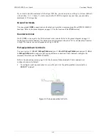
Figure 3-4. Schematic showing switch detection by digital channel Port A0 

For more information on digital signal connections 

For more information on digital signal connections and digital I/O techniques, refer to the 

Guide to Signal 

Connections

 (available on our web site at 

www.mccdaq.com/signals/signals.pdf

). 

Power terminals 

The USB +5 V connection (pin 30) is on the bottom screw terminal of the PMD-1024HLS. Refer to the 
pinout diagram on page 3-2 for the location of this terminal. This terminal draws power from the USB 
connector. The +5 volt screw terminal is a +5 volt output that is supplied by the connected computer.  

Caution!


The USB +5 V terminal is an output. Do not connect to an external power supply or you 
may damage the PMD-1024HLS and possibly the computer. 

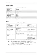
Just connecting the PMD-1024HLS to your computer draws 60 mA of current from the USB +5 V 
supply. Once you start running applications with the PMD-1024HLS, each DIO bit can draw up to 
15 mA. The maximum amount of +5 V current available for external use, over and above that required by 
the PMD-1024HLS, is the difference between the total current requirement of the PMD-1024HLS (based 
on the application), and the allowed current draw of the computer platform.  

The following power limits depend on whether you are sourcing current out of the PMD-1024HLS, or 
you are sinking current into the PMD-1024HLS. 

Output (source) current limits: desktop computers and self-powered hubs  

The maximum allowed current draw for a typical desktop computer and self-powered hub is 500 mA. For 
an application running on a PC or self-powered hub, this value yields a maximum user current of 500 mA 

 60 mA = 440 mA. Since each DIO line can output 15 mA maximum, 24 DIO 

×

 15 mA = 360 mA 

(maximum rating for the chips). 

Output (source) current limits: notebook computers and bus-powered hubs 

The maximum allowed current draw for a typical notebook computer and bus-powered hub is 100 mA.  

Because the PMD-1024HLS needs 60 mA from the USB +5 V supply, this leaves you with only 40 mA. 
If you want to use 15 mA per DIO line, you can only do so with two DIO lines. To overcome this 
limitation, an external self-powered hub can be used to supply the proper current level required for full 
output capability as noted above. 

Output (sink) current limits 

Each PMD-1024HLS DIO output can sink up to 64 mA. For an individual line, this is not a problem. But 
if you were to apply this maximum load to all 24 DIO lines, you would damage the PMD-1024HLS 
because the total amount of current is well over the 440 mA maximum (24 DIO 

×

 64 mA = 1536 mA 


1.54 A). 

3-4 

Summary of Contents for PMD-1024HLS

Page 1: ......

Page 2: ...PMD 1024HLS Personal Measurement Device brand USB based Digital I O Module User s Guide Document Revision 4 May 2005 Copyright 2005 Measurement Computing Corporation ...

Page 3: ...on that is damaged even due to misuse for only 50 of the current list price I O boards face some tough operating conditions some more severe than the boards are designed to withstand When a board becomes damaged just return the unit with an order for its replacement at only 50 of the current list price We don t need to profit from your misfortune By the way we honor this warranty for any manufactu...

Page 4: ...use No license is granted by implication or otherwise under any patent or copyrights of Measurement Computing Corporation All rights reserved No part of this publication may be reproduced stored in a retrieval system or transmitted in any form by any means electronic mechanical by photocopying recording or otherwise without the prior written permission of Measurement Computing Corporation Notice M...

Page 5: ...Hardware 2 1 Software 2 1 Documentation 2 2 Unpacking the PMD 1024HLS 2 2 Installing the software 2 2 Installing the hardware 2 2 Chapter 3 Functional Details 3 1 External components 3 1 USB connector 3 1 LED 3 1 Screw terminal wiring 3 2 Main connector and pin out 3 2 Digital I O terminals Port A0 to A7 Port B0 to B7 Port C0 to C7 3 3 Power terminals 3 4 Ground terminals 3 5 Counter terminal 3 5 ...

Page 6: ...names of manuals and help topic titles and to emphasize a word or phrase For example The InstaCal installation procedure is explained in the DAQ Software Quick Start Never touch the exposed pins or circuit connections on the board Where to find more information The following electronic documents provide information that can help you get the most out of your Personal Measurement Device brand PMD 10...

Page 7: ...e you are using the latest system software note in Chapter to make sure you are using the latest USB drivers 2 Installing the PMD 1024HLS The PMD 1024HLS is a high drive 24 line digital I O module that includes one 32 bit external event counter The PMD 1024HLS is powered by the 5 volt USB supply from your computer No external power is required An emulation of the 82C55 in mode 0 only sets the dire...

Page 8: ...erminal I O connector 4 4 8 8 8 8 8 1 Figure 1 2 PMD 1024HLS functional block diagram Software features The following software ships with the PMD 1024HLS free of charge InstaCal installation calibration and test utility TracerDAQ suite of virtual instruments SoftWIRE for Visual Studio NET graphical programming MCC DAQ Components for VS NET installed with SoftWIRE for VS NET For information on the ...

Page 9: ... DIP switches to set or interrupts to configure You can connect the PMD 1024HLS before or after you install the software and without powering down your computer first When you connect an HID to your system your computer automatically detects it and configures the necessary software You can connect and power multiple HID peripherals to your system using a USB hub You can connect your system to vari...

Page 10: ...he following components are included Hardware PMD 1024HLS USB cable 2 meter length Software The Measurement Computing Data Acquisition Software CD contains the following software InstaCal installation calibration and test utility TracerDAQ suite of virtual instruments SoftWIRE for VS NET SoftWIRE MCC DAQ Components for NET 2 1 ...

Page 11: ...ftware Quick Start for instructions on installing the software on the Measurement Computing Data Acquisition Software CD This booklet is available in PDF at www mccdaq com PDFmanuals DAQ Software Quick Start pdf Installing the hardware Be sure you are using the latest system software Before you connect the PMD 1024HLS make sure that you are using the latest versions of the USB drivers Before insta...

Page 12: ...24HLS should flash and then remain lit This indicates that communication is established between the PMD 1024HLS and your computer Caution Do not disconnect any device from the USB bus while the computer is communicating with the PMD 1024HLS or you may lose data and or your ability to communicate with the PMD 1024HLS If the LED turns off If the LED is lit but then turns off the computer has lost co...

Page 13: ...wer and communication The voltage output is system dependent and may be less than 5 V No external power supply is required LED The LED on the front of the housing indicates the communication status of the PMD 1024HLS It uses up to 5 mA of current and cannot be disabled explains the function of the PMD 1024HLS LED Table 3 1 Table 3 1 LED illumination LED Illumination Indication Steady green The PMD...

Page 14: ...nections Eight digital I O connections Port C0 to Port C7 One counter connection CTR Two power connections USB 5 V Three pull up and pull down connections Port A Pull up Pull down Port B Pull up Pull down and Port C Pull up Pull down Six ground connections GND Screw terminal pins 21 40 The screw terminals on the bottom edge of the PMD 1024HLS pins 21 to 40 provide the following connections 16 digi...

Page 15: ...o A7 Port B0 to B7 Port C0 to C7 Connect up to 24 digital I O lines to the screw terminal containing pins 1 to 8 Port C0 to Port C7 pins 21 to 28 Port A0 to Port A7 and pins 32 to 39 Port B0 to Port B7 Refer to the pinout diagram on page 3 2 for the location of these pins You can configure each digital port for either input or output When configured for input you can use the PMD 1024HLS digital I ...

Page 16: ...d on the application and the allowed current draw of the computer platform The following power limits depend on whether you are sourcing current out of the PMD 1024HLS or you are sinking current into the PMD 1024HLS Output source current limits desktop computers and self powered hubs The maximum allowed current draw for a typical desktop computer and self powered hub is 500 mA For an application r...

Page 17: ...Refer to the pinout diagram on page 3 2 for the location of this terminal The internal counter increments when the TTL levels transition from low to high The counter can count frequencies of up to 1 MHz Pull up pull down terminals You can wire pin 11 Port C Pull up Pull down pin 13 Port B Pull up Pull down and pin 15 Port A Pull up Pull down to support a pull up or pull down connection These termi...

Page 18: ...iring options Figure 3 8 Schematic showing Port B pull up pull down wiring options Figure 3 9 Schematic showing Port C pull up pull down wiring options USB 5 V GND DIO 7 Port C7 DIO 6 Port C 6 DIO 5 Port C5 DIO 4 Port C4 DIO 3 Port C3 DIO 2 Port C2 DIO 1 Port C1 DIO 0 Port C0 Port C Pin 11 Pull up Pull down GND DIO 7 Port A7 DIO 6 Port A6 DIO 5 Port A5 DIO 4 Port A4 DIO 3 Port A3 DIO 2 Port A2 DIO...

Page 19: ...are root port hubs All externally powered root port hubs i e desktop PC s provide up to 500 mA of current for a USB device In this configuration all 24 digital outputs of the PMD 1024HLS can source their per pin maximum of 15 mA This provides a total requirement of 15 mA 24 360 mA Combining this with the PMD 1024HLS operating current of 60 mA a fully loaded current draw of 420 mA is realized Bus p...

Page 20: ...terminals pins 10 14 and 30 4 4 V min 5 25 V max Connected to Self powered hub Externally powered root port hub 350 mA total output source current USB 5 V power output current Note 7 Connected to Bus powered hub Battery powered root port hub 60 mA total output source current Hold current 350 mA typical Trip current 700 mA typical Trip recovery time 100 mS max USB 5 V overcurrent protection Resetta...

Page 21: ...e A B cable UL type AWM 2527 or equivalent min 24 AWG VBUS GND min 28 AWG D D User connection length 3 meters max Main connector and pin out Table 4 7 Connector specifications Connector type Screw terminal Wire gauge range 30 16 AWG Table 4 8 Connector pin out Pin Signal Name Pin Signal Name 1 Port C0 21 Port A0 2 Port C1 22 Port A1 3 Port C2 23 Port A2 4 Port C3 24 Port A3 5 Port C4 25 Port A4 6 ...

Page 22: ... 11 Radiated and Conducted emissions Immunity EN61326 Annex A EN 61000 4 2 1995 Electrostatic Discharge immunity Criteria C EN 61000 4 3 1997 Radiated Electromagnetic Field immunity Criteria A EN 61000 4 8 1995 Power Frequency Magnetic Field immunity Criteria A Power line and I O tests to EN61000 4 4 EN61000 4 5 EN61000 4 6 and EN61000 4 11 were not required The device is DC powered from an I O ca...

Page 23: ...Measurement Computing Corporation 16 Commerce Boulevard Middleboro Massachusetts 02346 508 946 5100 Fax 508 946 9500 E mail info mccdaq com www mccdaq com ...

Reviews: