USB-1808X-OEM User's Guide
Specifications
24
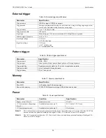
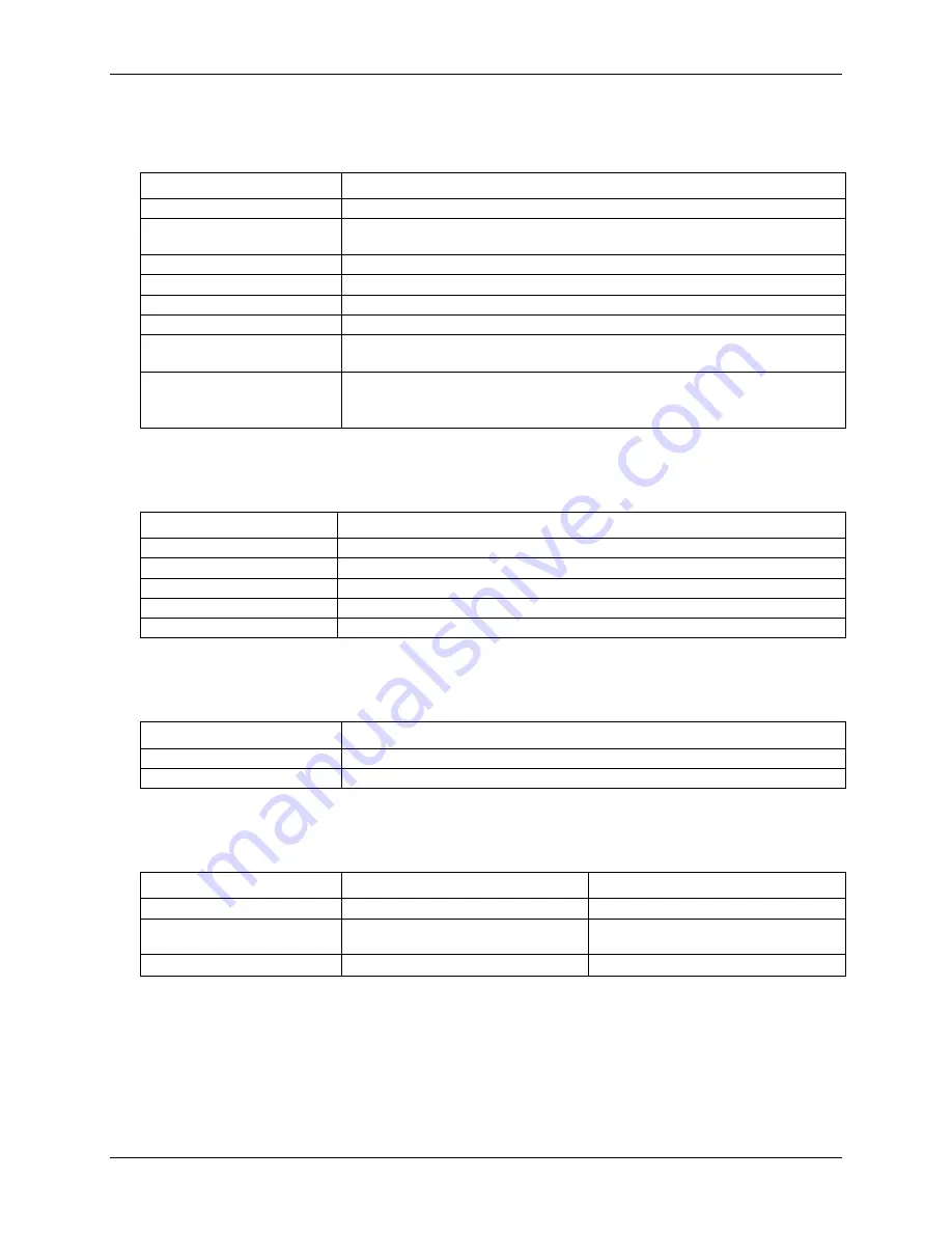
External trigger
Table 15. External trigger specifications
Parameter
Specification
Trigger source
ITRIG for inputs, OTRIG for outputs
Trigger mode
Software programmable for edge or level sensitive, rising or falling edge, high or low
level. Power on default is edge sensitive, rising edge.
Trigger latency
1 µs + 1 clock cycle max
Trigger pulse width
100 ns min
Input type
Schmitt trigger, 33
Ω series resistor and 49.9
kΩ pull
-down to ground
Schmitt trigger hysteresis
0.4 V to 1.2 V
Input high voltage
2.2 V min
5.5 V absolute max
Input low voltage
1.5 V max
–0.5 V absolute min
0 V recommended min
Pattern trigger
Table 16. Pattern trigger specifications
Parameter
Specification
Trigger source
DIO0 – DIO3
Trigger types
Above pattern, Below pattern, Equal pattern, or Not equal pattern
Trigger stability
Digital port must be stable for 50 ns to be recognized as a pattern
Trigger bit width
Up to 4, adjustable through bitmask
Trigger latency
Up to 1 scan period
Memory
Table 17. Memory specifications
Parameter
Specification
Data FIFO
4 kS analog input/2 kS analog output
Non-volatile memory
32 KB (28 KB firmware storage, 4 KB calibration/user data)
Power
Table 18. Power specifications
Parameter
Condition
Specification
Supply current (Note 3)
Quiescent current
305 mA
+VO user output voltage range
(Note 4)
Available at connector pin 13
4.5 V min to 5.25 V max
+VO user output current
Available at connecter pin 13
10 mA max
Note 3:
This is the total quiescent current requirement for the device that includes up to 10 mA for the status LED. This
does not include any potential loading of the digital I/O bits, +VO terminal, or the AOUTx outputs.
Note 4:
The +4.5 V min limit includes the +VO 10 mA load, it does not include any potential loading of the digital I/O
bits or the AOUTx outputs.

