USB-2416-4AO User's Guide
Functional Details
16
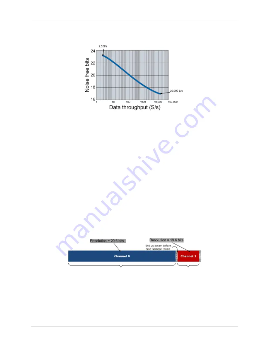
Figure 10 below illustrates this inverse relationship. This graph applies to the A/D converter only—do not
expect this level of performance from the USB-2416 itself.
Figure 10. USB-2416-4AO A/D converter data rate vs. noise graph
If low noise is your main concern, you can operate the USB-2416-4AO at very low data rates starting from 2.5
S/s. At low rates, much of the noise is averaged out of the data, and issues such as reference noise become less
important.
At higher data rates, higher-frequency noise sources are not averaged out and begin to be troublesome. These
noise sources include the noise inherent in the A/D converter itself, which is not reducible.
Since thermocouples can pick up noise in your environment, select a data rate based on the primary noise
frequency. For example, to reduce the effect of 60 Hz noise, select a data rate of 60 (or a sub-multiple of 60,
such as 10 or 20).
Multiple-channel throughput rates
When setting different sample rates for different channels, be aware that the all channels will be sampled within
the same
sample window
based on the channel with the lowest sample rate.
For example, if you set a 10 Hz data rate for channel 0, and a 50 Hz data rate for channel 1, basically, both
channels pass the same number of samples per second to the host computer. However, more averaging is
performed on channel 0's samples; therefore, channel 0 is sampled at a higher resolution.
The USB-2416-4AO's A/D converter performs averaging, and the number of averages equals
30,000/data rate.
In this example, channel 0 is sampled 3000 times over 100 ms, and all samples are averaged into one sample.
Then, channel 1 is sampled 600 times over 20 ms, and samples are likewise averaged into one sample.
The final samples are available to you at a maximum rate of about 8 Hz (8.245 Hz).
Figure 11. USB-2416-4AO data rate vs. resolution example
Input isolation
The USB-2416-4AO is an isolated data acquisition device. The analog input, digital I/O, counters, and all the
digital control/timing are referenced to an isolated ground as shown in the figure below. This ground is
physically and electrically separate from the ground use by the circuit connected to the system bus interface.
Isolation provides a barrier between the host computer and potentially hazardous voltages by physically and
electrically separating two parts of the measurement device.


