background image


Table of Contents 

Preface


About this User's Guide ....................................................................................................................... 4


What you will learn from this user's guide ......................................................................................................... 4


Conventions in this user's guide ......................................................................................................................... 4


Where to find more information ......................................................................................................................... 4


Chapter 1


Introducing the USB-DIO96H/50 .......................................................................................................... 5


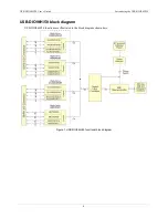
USB-DIO96H/50 block diagram ........................................................................................................................ 6


Chapter 2


Installing the USB-DIO96H/50 .............................................................................................................. 7


Unpacking........................................................................................................................................................... 7


Installing the software ........................................................................................................................................ 7


Connecting the external power supply ................................................................................................................ 7


Installing the hardware ....................................................................................................................................... 7


Chapter 3


Functional Details ................................................................................................................................. 8


Components ........................................................................................................................................................ 8


USB connector .................................................................................................................................................................. 8


External power connector ................................................................................................................................................. 8


Molex connector ............................................................................................................................................................... 8


Power source jumper JP2 .................................................................................................................................................. 9


USB LED .......................................................................................................................................................................... 9


PWR LED ......................................................................................................................................................................... 9


Header connectors ............................................................................................................................................................10


Pull-up/down switches .....................................................................................................................................................10


Signal connections ............................................................................................................................................ 10


Compatible cables and accessory products ......................................................................................................................11


Digital I/O (FIRSTPORTA Bit 0 through FOURTHPORTC Bit 7) ................................................................................12


Power outputs ..................................................................................................................................................................12


Ground .............................................................................................................................................................................12


Mechanical drawings ........................................................................................................................................ 13


Chapter 4


Specifications ...................................................................................................................................... 14


Digital input/output........................................................................................................................................... 14


Power ................................................................................................................................................................ 15


Environmental .................................................................................................................................................. 15


USB specifications ........................................................................................................................................... 15


Data transfer rates ............................................................................................................................................. 15


Mechanical ....................................................................................................................................................... 16


Signal connectors .............................................................................................................................................. 16


P1 .....................................................................................................................................................................................16


P2 .....................................................................................................................................................................................17


Declaration of Conformity .................................................................................................................. 18


Summary of Contents for USB-DIO96H/50

Page 1: ...USB DIO96H 50 High drive Digital I O User s Guide September 2019 Rev 10 Measurement Computing Corporation Hardware Revision 2 ...

Page 2: ...tted in any form by any means electronic mechanical by photocopying recording or otherwise without the prior written permission of Measurement Computing Corporation Notice Measurement Computing Corporation does not authorize any Measurement Computing Corporation product for use in life support systems and or devices without prior written consent from Measurement Computing Corporation Life support ...

Page 3: ...dware 7 Chapter 3 Functional Details 8 Components 8 USB connector 8 External power connector 8 Molex connector 8 Power source jumper JP2 9 USB LED 9 PWR LED 9 Header connectors 10 Pull up down switches 10 Signal connections 10 Compatible cables and accessory products 11 Digital I O FIRSTPORTA Bit 0 through FOURTHPORTC Bit 7 12 Power outputs 12 Ground 12 Mechanical drawings 13 Chapter 4 Specificati...

Page 4: ...ional information related to the subject matter Caution Shaded caution statements present information to help you avoid injuring yourself and others damaging your hardware or losing your data bold text Bold text is used for the names of objects on a screen such as buttons text boxes and check boxes italic text Italic text is used for the names of manuals and help topic titles and to emphasize a wo...

Page 5: ...ssociated DIP switches to drive the ports high during power up and reset You can optionally set these switches for a pull down configuration All I O bits are set to input mode on power up and reset The USB DIO96H 50 is shipped in a rugged metal enclosure that you can mount on a DIN rail or on a bench refer to Figure 9 on page 13 The USB DIO96H 50 is powered by an external 5 V regulated power suppl...

Page 6: ...B DIO96H 50 User s Guide Introducing the USB DIO96H 50 6 USB DIO96H 50 block diagram USB DIO96H 50 functions are illustrated in the block diagram shown here Figure 1 USB DIO96H 50 functional block diagram ...

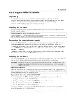
Page 7: ...ion of this connector The PWR LED lights up when 5 V power is supplied to the USB DIO96H 50 If the voltage supply is less than 4 1 V or more than 5 6 V the PWR LED does not turn on Installing the hardware Connect the USB DIO96H using the cable provided to a USB port on a computer running Windows Windows finds and installs the device driver automatically and notifies you that the device is ready to...

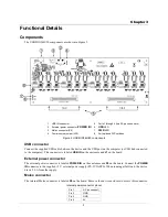
Page 8: ...B port on the computer or USB hub connected to the computer This connector is labeled USB IN on the enclosure and J1 on the board External power connector The external power connector is labeled POWER IN on the enclosure and P5 on the board Connect the POWER IN connector to the supplied 5 V external power supply PS 5V3AEPS When running at full load the device draws 2 6 A from the supply Molex conn...

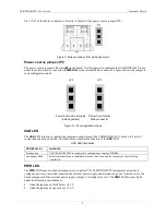
Page 9: ...ication status of the USB DIO96H 50 It uses up to 5 mA of current and cannot be disabled The table below explains the function of the USB LED USB LED illumination LED Behavior Indication Steady green The USB DIO96H 50 is connected to a computer or external USB hub Continuous blink Initial communication is established between the device and the computer or data is being transferred PWR LED The PWR ...

Page 10: ...s the following connections 48 DIO connections THIRDPORTA Bit 0 through FOURTHPORTC Bit 7 one ground connection GND one power connection 5V 50 pin connector pinout P1 Signal name Pin Pin Signal name GND 50 49 5V FIRSTPORTC Bit 0 48 47 FIRSTPORTC Bit 1 FIRSTPORTC Bit 2 46 45 FIRSTPORTC Bit 3 FIRSTPORTC Bit 4 44 43 FIRSTPORTC Bit 5 FIRSTPORTC Bit 6 42 41 FIRSTPORTC Bit 7 FIRSTPORTB Bit 0 40 39 FIRST...

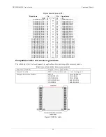
Page 11: ... 3 FOURTHPORTC Bit 4 70 69 FOURTHPORTC Bit 5 FOURTHPORTC Bit 6 68 67 FOURTHPORTC Bit 7 FOURTHPORTB Bit 0 66 65 FOURTHPORTB Bit 1 FOURTHPORTB Bit 2 64 63 FOURTHPORTB Bit 3 FOURTHPORTB Bit 4 62 61 FOURTHPORTB Bit 5 FOURTHPORTB Bit 6 60 59 FOURTHPORTB Bit 7 FOURTHPORTA Bit 0 58 57 FOURTHPORTA Bit 1 FOURTHPORTA Bit 2 56 55 FOURTHPORTA Bit 3 FOURTHPORTA Bit 4 54 53 FOURTHPORTA Bit 5 FOURTHPORTA Bit 6 5...

Page 12: ...al signals Additional information about digital signal connections and I O techniques is available in the Guide to DAQ Signal Connections available on our web site at www mccdaq com support DAQ Signal Connections aspx Digital I O FIRSTPORTA Bit 0 through FOURTHPORTC Bit 7 You can connect 96 digital I O lines to the two 50 pin connectors Each digital port group is divided into two 8 bit ports and t...

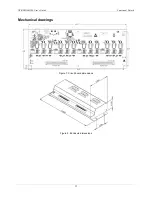
Page 13: ...USB DIO96H 50 User s Guide Functional Details 13 Mechanical drawings Figure 7 Circuit board dimensions Figure 8 Enclosure dimensions ...

Page 14: ...44A Input 74ACT373 Configuration Eight banks of 8 eight banks of 4 programmable by bank as input or output Pull up pull down High impedance pull up pull down selectable via DIP switch for each digital input port Number of I O 96 Output high 2 0 V min 24 mA Output low 0 5 V max 64 mA Input high 2 0 V min 5 5 V max Input low 0 8 V max 0 5 V absolute min Input impedance 47 kΩ series resistance Source...

Page 15: ...fication applies at barrel plug power input The power supply provided with the board meets this specification at the rated total power supply current If a different power supply is used small line resistances could cause significant voltage drop between the power supply and the barrel plug input Environmental Table 3 Environmental specifications Parameter Specification Operating temperature range ...

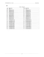
Page 16: ...44 FIRSTPORTC Bit 4 43 FIRSTPORTC Bit 5 42 FIRSTPORTC Bit 6 41 FIRSTPORTC Bit 7 40 FIRSTPORTB Bit 0 39 FIRSTPORTB Bit 1 38 FIRSTPORTB Bit 2 37 FIRSTPORTB Bit 3 36 FIRSTPORTB Bit 4 35 FIRSTPORTB Bit 5 34 FIRSTPORTB Bit 6 33 FIRSTPORTB Bit 7 32 FIRSTPORTA Bit 0 31 FIRSTPORTA Bit 1 30 FIRSTPORTA Bit 2 29 FIRSTPORTA Bit 3 28 FIRSTPORTA Bit 4 27 FIRSTPORTA Bit 5 26 FIRSTPORTA Bit 6 25 FIRSTPORTA Bit 7 ...

Page 17: ...it 0 81 THIRDPORTA Bit 1 80 THIRDPORTA Bit 2 79 THIRDPORTA Bit 3 78 THIRDPORTA Bit 4 77 THIRDPORTA Bit 5 76 THIRDPORTA Bit 6 75 THIRDPORTA Bit 7 74 FOURTHPORTC Bit 0 73 FOURTHPORTC Bit 1 72 FOURTHPORTC Bit 2 71 FOURTHPORTC Bit 3 70 FOURTHPORTC Bit 4 69 FOURTHPORTC Bit 5 68 FOURTHPORTC Bit 6 67 FOURTHPORTC Bit 7 66 FOURTHPORTB Bit 0 65 FOURTHPORTB Bit 1 64 FOURTHPORTB Bit 2 63 FOURTHPORTB Bit 3 62 ...

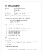
Page 18: ...cordance to the following standards EMC Emissions EN 61326 1 2013 IEC 61326 1 2012 Class A EN 55011 2009 A1 2010 IEC CISPR 11 2009 A1 2010 Group 1 Class A Immunity EN 61326 1 2013 IEC 61326 1 2012 Controlled EM Environments EN 61000 4 2 2008 IEC 61000 4 2 2008 EN 61000 4 3 2010 IEC61000 4 3 2010 EN 61000 4 4 2012 IEC61000 4 4 2012 EN 61000 4 5 2014 IEC61000 4 5 2014 EN 61000 4 6 2013 IEC61000 4 6 ...

Page 19: ...ion NI Hungary Kft 10 Commerce Way H 4031 Debrecen Hátar út 1 A Hungary Norton Massachusetts 02766 Phone 36 52 515400 508 946 5100 Fax 36 52 515414 Fax 508 946 9500 http hungary ni com debrecen E mail info mccdaq com www mccdaq com ...

Reviews: