Thermocouple connec ons
A thermocouple consists of two dissimilar metals that are joined together at one end. When the junc on of the
metals is heated or cooled, a voltage is produced that correlates to temperature.
The WebDAQ 316 supports type J, K, S, R, B, E, T, N thermocouples (TC), and provides overvoltage protec on
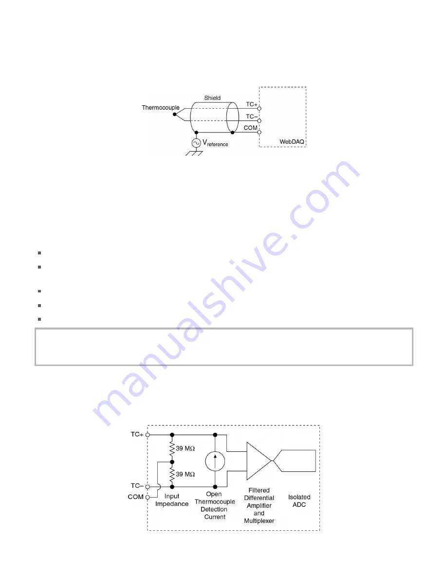
between any two inputs. A typical thermocouple connec on is shown in the following figure.
Figure 6. Typical thermocouple connec on
Connect the shield to a common mode voltage reference on the thermocouple. A valid reference is voltage
within ±1.2 V of all the connected thermocouples.
Minimizing thermal gradients
Changes in the ambient air temperature near the thermocouple connectors or a thermocouple wire conduc ng
heat directly to terminal junc ons can cause thermal gradients. Observe the following guidelines to minimize
thermal gradients and improve system accuracy:
Use small-gauge thermocouple wire. Smaller wire transfers less heat to or from the terminal junc on.
Run thermocouple wiring together near the spring terminal connector to maintain a consistent
temperature.
Avoid running thermocouple wires near hot or cold objects.
Minimize adjacent heat sources and air flow across the terminals.
Keep the ambient temperature as stable as possible.
Increasing the thermocouple length
If you need to increase the length of your thermocouple, use the same type of TC wires to minimize the
error introduced by thermal EMFs.
Analog input circuitry
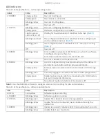
Each channel passes through a differen al filter and then is mul plexed and sampled by a 24-bit ADC. The
channels share a common ground (COM) that is isolated from the digital subsystem.
The circuitry for one thermocouple channel is shown in here.
Figure 7. Input circuitry of one TC channel
WebDAQ 316 User's Guide
page 11


