DC5xD MK3 GENSET CONTROLLER USER MANUAL
10
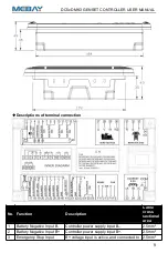
emergency stop normal closed button.
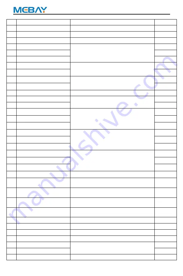
4
Fuel Output
+VE output, Max 16Amp
1.5mm
2
5
Crank Output
+VE output, Max 16Amp.
1.5mm
2
6
Aux. Ouput 1
+VE output, Max 5Amp.
1.5mm
2
7
Aux. Ouput 2 Normal close
Passive Output, Max 5Amp.
1.5mm
2
8
Aux. Ouput 2 Common
1.5mm
2
9
Aux. Ouput 2 Normal open
1.5mm
2
10 Aux.Output 3
Passive normally open output, Max 5Amp.
1.5mm
2
11 Aux.Output 3
1.5mm
2
12 Aux.Output 4
Passive normally open output, Max 5Amp.
1.5mm
2
13 Aux.Output 4
1.5mm
2
14 Charging excitation output
+VE output, Max 0.9Amp.
1.0mm
2
15 Speed sensor -
Use a shielded wire to connect the speed
sensor.
1.0mm
2
16 Speed
1.0mm
2
17 Temperature Sensor
Connect sensor input.
1.0mm
2
18 Oil pressure sensor
1.0mm
2
19 Fuel level sensor
1.0mm
2
20 Aux. Input 1
The grounding is valid according to the
function selection switch input.
1.0mm
2
21 Aux. Input 2
1.0mm
2
22 Aux. Input 3
1.0mm
2
23 Load CT Secondary L1
Current Transformer Secondary Rated 5A.
1.5mm
2
24 Load CT Secondary L2
1.5mm
2
25 Load CT Secondary L3
1.5mm
2
26 Load CT Secondary ICOM Connect to the common.
1.5mm
2
27 Generator Voltage U
Connected to the power generation output R
phase.
1.0mm
2
28 Generator Voltage V
Connected to the power generation output S
phase.
1.0mm
2
29 Generator Voltage W
Connected to the power generation output T
phase.
1.0mm
2
30 Generator Voltage N2
Connected to the power generation output N
phase.
1.0mm
2
31 Mains Voltage R
Connected to the mains U phase.
1.0mm
2
32 Mains Voltage S
Connected to the mains V phase.
1.0mm
2
33 Mains Voltage T
Connected to the mains W phase.
1.0mm
2
34 Mains Voltage N1
Connected to the mains N phase.
1.0mm
2
38 Aux. Input 4
The grounding is valid according to the
function selection switch input.
1.0mm
2
39 Aux. Input 5
1.0mm
2
40 Sensor common GND
Connect the battery negative or outer.
1.0mm
2


