background image

DC8xD MK3 GENSET CONTROLLER USER MANUAL

22

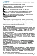
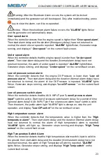
set to "

warning

", When the oil pressure sensor is detected to be disconnected,Then

start warning delay and the duration (2S) have not returned to normal, the warning of

Oil pressure sensor disconnected warning is reported. "

WARNING

" lights will light up,

Generators will not stop, displays "

OP sensor open

" on the current fault screen.

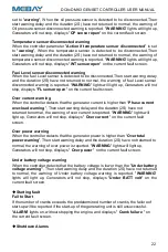
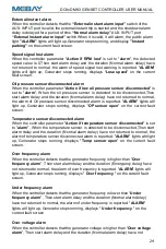
Temperature sensor disconnected warning

When the controller parameter "

Action if temperature sensor disconnected

" is set

to "

warning

", When the temperature sensor is detected to be disconnected,Then

start warning delay and the duration (2S) have not returned to normal, the warning of

temperature sensor disconnected warning is reported. "

WARNING

" lights will light up,

Generators will not stop, displays "

WT sensor open

" on the current fault screen.

Fuel Level sensor disconnected warning

When the fuel Level sensor is detected to be disconnected,Then start warning delay

and the duration (2S) have not returned to normal, the warning of fuel Level sensor

disconnected warning is reported. "

WARNING

" lights will light up, Generators will not

stop, displays "

FL sensor open

" on the current fault screen.

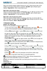
Over current warning

When the controller detects that the generator current is higher than “

Phase current

over-load warning

”, Then start warning delay and the duration (2S) have not

returned to normal, the warning of over current is reported. "

WARNING

" lights will

light up, Generators will not stop, displays "

Over current

" on the current fault

screen.

Over power warning

When the controller detects that the generator power is higher than “

Over total

power warning

”, Then start warning delay and the duration (2S) have not returned to

normal, the warning of over power is reported. "

WARNING

" lights will light up,

Generators will not stop, displays "

Over power

" on the current fault screen.

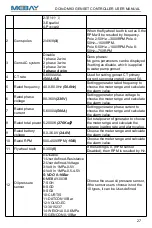
Under battery voltage warning

When the controller detects that the battery voltage is lower than the "

Under battery

voltage warning"

, Then start warning delay and the duration (2S) have not returned

to normal, the warning of Under battery voltage warning is reported. "

WARNING

"

lights will light up, Generators will not stop, displays "

Under BATT volt

" on the

current fault screen.

Starting fault

Fail to Start

If the number of cranks exceeds the predetermined number of cranks, the failure of

start-up will be reported if the start-up of the generating unit is still unsuccessful.

"

ALARM

" lights on, without stopping the engine, and displays "

Crank failure

" on

the current fault screen.

Shutdown Alarms

Summary of Contents for DC8-D MK Series

Page 1: ...DC8xD MK3 GENSET CONTROLLER USER MANUAL DC80D MK3 DC82D MK3 ...

Page 2: ... V1 0 2020 10 1 Original release 2 V1 1 2021 02 01 Name of unified input and output port Chongqing MEBAY Technology Co Ltd Add No6 2 Building 4 Gangan Rd Jiangbei District Chongqing Tel 86 23 6869 3061 Fax 86 23 6765 8207 Web http www mebay cn http www cqmb cn E_mail sales mebay cn ...

Page 3: ...wise it may cause the equipment not to work correctly Be care It is indicated that potential hazards can damage equipment without proper precautions Warning It is indicated if appropriate preventive measures are not taken potentially dangerous situations may result in death serious personal injury or significant property losses ...

Page 4: ...amage to related equipment 5 The engine must have an overspeed protection device independent of the controller system to avoid casualties or other damage caused by engine out of control 6 After the installation of the controller is completed please verify that all protection functions are valid Be Care 1 Please keep the good connection of the power supply of the controller Do not share the connect...

Page 5: ...operation instruction 18 9 Warnings and Shutdown Alarms 21 10 Parameter setting 26 11 Fault finding 35 Notes 1 All rights reserved No part of this duplication may be reproduced in any material form including photocopying or storing in any medium by electronic means or others without the written permission of the copyright holder 2 MEBAY Technology reserves the rights to change the contents of this...

Page 6: ...table for the automation system composed by mains and genset DC80DR MK3 Based on DC80D MK3 it adds RS485 port DC82DR MK3 Based on DC82D MK3 it adds RS485 port Dual core 32bit high performance single chip microcomputer 4 3inch TFT colorful big screen LCD Available in 5 languages user s language set if necessary Indicator and number display through UI surface Acrylic material is adapted to protect t...

Page 7: ...gine battery voltage Charging voltage Mains Frequency only for DC82D MK3 Mains phase voltage L N only for DC82D MK3 Mains phase voltage L L only for DC82D MK3 Generator 3 Phase voltage L N Generator 3 Phase voltage L L Generator phase Generator 3 phase current A Generator Frequency Hz Generator Power Factor COS φ Generator active power KW Generator apparent power KVA Generator reactive power K Var...

Page 8: ...mp DC VE Supply voltage Start Relay Output Max 16Amp DC VE Supply voltage AUX OUPUT1 Max 5Amp DC VE Supply voltage AUX OUPUT2 Max 5Amp DC VE Supply voltage AUX OUPUT3 Max 5Amp DC VE Supply voltage AUX OUPUT4 5AMP Non contact normal close output AUX OUPUT5 5AMP Non contact normal open output Excitation output Max 0 9AMP DC VE supply voltage Switch value input Available if connecting with Battery Wo...

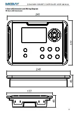
Page 9: ...DC8xD MK3 GENSET CONTROLLER USER MANUAL 8 5 Overall Dimension and Wiring Diagram Overall Dimension 241 177 45 241 177 45 ...

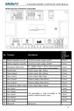
Page 10: ...to emergency stop normal closed button 2 5mm2 4 Fuel Output Active output Max 16Amp 1 5mm2 5 Crank Output Active output Max 16Amp 1 5mm2 6 Aux Ouput1 Active output Max 5Amp 1 5mm2 7 Aux Ouput2 Passive Output Max 5Amp 1 5mm2 8 Aux Ouput3 Passive Output Max 5Amp 1 5mm2 9 Charging excitation output Active output Max 0 9Amp 1 0mm2 10 Aux Input1 The grounding is valid according to the function selectio...

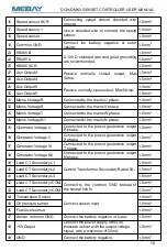
Page 11: ...nnected to the mains N phase 1 0mm2 35 Generator Voltage U Connected to the power generation output R phase 1 0mm2 36 Generator Voltage V Connected to the power generation output S phase 1 0mm2 37 Generator Voltage W Connected to the power generation output T phase 1 0mm2 38 Generator Voltage N2 Connected to the power generation output N phase 1 0mm2 39 Load CT Secondary L1 Current Transformer Sec...

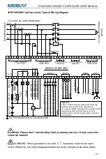
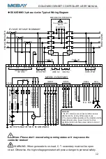
Page 12: ... S1_OIL PRESSURE 11 10 9 45 44 5 4 3 2 1 46 37 T 36 35 S R 41 CT2 38 N1 MODEL DC80D MK3 BATTERY FUSE 10A FUSE 20A EMERGENCY INPUTS FUEL CRANK BATTERY NEGATIVE MUST BE GROUNDED SWITCH 40 39 CT1 CT3 COM 17 18 D 42 12 6 13 14 47 ALT P1 P2 S1S2 P1 P2 S1S2 P1 P2 S1S2 R S T N1 7 8 16 WL AUX OUTPUT 1 MAX 5A MAX 16A 30 33 W 32 31 V U 34 N2 27 29 28 MAX 5A G MAX 5A DC8 36V 15 19 24 25 23 B A SCR RS485 MPU ...

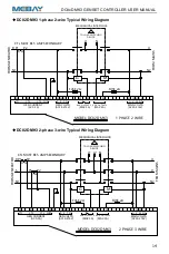
Page 13: ... V W N2 CTs MUST BE 5 AMP SECONDARY FROM GENERATOR FUSE 2A FUSE 2A MAX 5A MAX 5A AC30 276V AC 0 5A GEN CURRENT GEN VOLTS AUX OUTPUT 5 AUX OUTPUT 4 AC30 276V MAIN VOLTS MODEL DC82D MK3 GND AUX S2_COOLANT TEMP AUX S3_FUEL LEVEL AUX INPUT 5_LOW COOLANT LEVEL ALARM AUX INPUT 2_HIGH COOLANT TEMP ALARM AUX INPUT 4_LOW FUEL LEVEL WARNING AUX INPUT 3_LOW OIL PRESSURE ALARM AUX INPUT 1_REMOTE START AUX S1_...

Page 14: ...1 30 33 W 32 31 V U 34 N2 29 G 43 AC 0 5A GEN CURRENT GEN VOLTS MAIN VOLTS FUSE 2A 1 PHASE 2 WIRE AC30 276V AC30 276V 27 28 MAX 5A MAX 5A AUX OUTPUT 5 AUX OUTPUT 4 CTs MUST BE 5 AMP SECONDARY FROM GENERATOR TO LOAD SWITCHING DEVICE 37 T 36 35 S R 41 CT2 38 N1 MODEL DC80D MK3 40 39 CT1 CT3 COM 42 P1 P2 S1S2 P1 P2 S1S2 R S N1 30 33 W 32 31 V U 34 N2 29 G 43 AC 0 5A GEN CURRENT GEN VOLTS MAIN VOLTS F...

Page 15: ...L DC82D MK3 1 PHASE 2 WIRE T S R CT2 N1 CT1 CT3 COM W V U N2 MAX 5A MAX 5A AC30 276V AC 0 5A GEN CURRENT GEN VOLTS AUX OUTPUT 5 AUX OUTPUT 4 AC30 276V MAIN VOLTS FROM MAINS MECHANICAL INTERLOCK TO LOAD SWITCHING DEVICE 37 36 35 41 38 40 39 42 P1 P2 S1S2 P1 P2 S1S2 R S N1 30 33 32 31 34 27 29 28 G 43 M L1 L2 N U V N2 CTs MUST BE 5 AMP SECONDARY FROM GENERATOR FUSE 2A FUSE 2A MODEL DC82D MK3 2 PHASE...

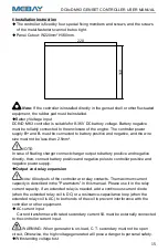
Page 16: ...utput to battery positive and negative directly then connect battery positive and negative poles to controller positive and negative power supply Output and relay expansion Note All outputs of the controller are relay contacts The maximum current capacity is described in the Parameters in this manual Please use it in the relay current capacity If an extended relay is needed add a continuous curren...

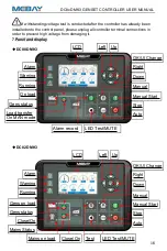
Page 17: ...o prevent high voltage from damaging it 7 Panel and display DC80D MK3 DC82D MK3 Right OK UI Change Down LED Test MUTE Alarm record Stop Manual Start Manual Auto Running Warning Alarm Close On Gens on load Gens status Mains Status Right OK UI Change Down Manual Auto Stop Manual Start LCD Left Up Gens status Running Warning Alarm On load Load transfer On MAN mode LCD Left Up Mains on load Close On T...

Page 18: ...o test if the auto start is in normal status LED Test Warning clear Test if all LED lights are ok pressing this key to test if all lighted all off when loosen it Under warning pressing this key can clear warning and controller will re check warning Under alarm pressing this key can clear the buzzer call Pressing this key in 3 seconds can clear the buzzer call pressing it again in 3 seconds can rec...

Page 19: ... teeth saved successfully Alarm records checking DC8xD MK3 controller can save 40 group of alarm records which contains the alarm record data includes detailed data such as alarm time generator parameters engine parameters etc How to check the alarm records 1 Enter alarm record page a DC80D MK3 under stop mode press to come into alarm records page b DC82D MK3 press and simultaneously to come into ...

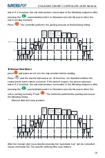
Page 20: ...ss and the test file indicator is on At this time it is detected whether the connection of each sensor is normal If the sensor is open the sensor opens an alarm If it is normal the unit start process is executed in the following sequence after pressing the automatically switch to Generator provide the power when the unit is running normally Press The controller performs the parking process at the ...

Page 21: ...status in real time DC82D MK3 is available When the remote start signal fails and the mains provide the power returns to normal the shutdown process after the loop time delay is performed DC82D MK3 is available Auto start and stop process Auto Start delay 0RPM Idle Rated speed Pre heat delay 5S 5S Long est pre oil supply delay 0S Start Crank delay 2S Crank test time 8S Crank rest time 10S 8S Safe ...

Page 22: ...eturned to normal the warning of Low fuel level warning is reported WARNING lights will light up Generators will not stop displays Low fuel level A on the current fault screen Low fuel level switch warning When the controller detects that the AUX INPUT Low fuel level warning input switch is active it starts warning delay and lasts for 2 seconds When the Low fuel level warning input switch is enabl...

Page 23: ...ver current warning When the controller detects that the generator current is higher than Phase current over load warning Then start warning delay and the duration 2S have not returned to normal the warning of over current is reported WARNING lights will light up Generators will not stop displays Over current on the current fault screen Over power warning When the controller detects that the gener...

Page 24: ...duration Normal alarm delay have not returned to normal the alarm of low Oil Pressure is reported ALARM lights flicker Generator stops running and displays Low OP sensor on the current fault screen Low oil pressure switch alarm When the controller detects that the AUX INPUT port Low oil pressure alarm input switch is active Start low oil pressure switch alarm delay for a period of time general ala...

Page 25: ...RM lights will light up Generator stops running displays OP sensor open on the current fault screen Temperature sensor disconnected alarm When the controller parameter Action if temperature sensor disconnected is set to alarm When the temperature sensor is detected to be disconnected Then start alarm delay and the duration Normal alarm delay have not returned to normal the alarm of temperature sen...

Page 26: ...er on the current fault screen Maintenance Expiration Alarm When the action after the primary maintenance expired set as alarm When the countdown to maintenance is detected as 0 Then start warning delay and the duration Normal alarm delay have not returned to normal the warning of Maintenance expiration is reported ALARM lights on Generator stops running and displays Maintain end on the current fa...

Page 27: ... reduce number 1 press to turn the digit into right press to turn the digit into left press once done Then system comes into menu after confirmation of password setting The screen will display error if password is wrong The correct password should be put after pressing any button 3 Press to turn the digit into upper position press to turn the digit into lower position press to get into parameters ...

Page 28: ...he meter range and calculate the alarm value 7 Rated phase current 5 6000A 500A Setting generator phase current to choose the meter range and calculate the alarm value 8 Rated total power 5 2000K 276Kw Set total power of generator to choose the meter range and calculate the average loading rate and alarm value 9 Rated battery voltage 8 0 36 0V 24 0V Choose the meter range and calculate the alarm v...

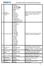
Page 29: ...200 0Ω If the sensor users choose is not the 10 types it can be User defined 15 Action if over current Warning Alarm and stop Trip stop If the system is set as trip stop then the unloading procession shall be acted then delays 1S and then stops to alarm 16 Action if over power Warning Alarm and stop Trip stop If the system is set as trip stop then the unloading procession shall be acted and then s...

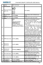
Page 30: ...owever successful parking requires several conditions to be met at the same time 24 RPM disconnect 0 200 24 Rated RPM multiplying by this value is regarded as crank success condition When the RPM is over the condition value then system regards it as crank success motor escaped 25 Frequency disconnect 0 200 28 Rated frequency multiplying by this value is regarded as crank success condition When the...

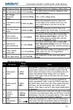
Page 31: ... charge failure are all invalid during this time except for emergency stop and over speed 7 Start idle time 0 3600 0s 5 0s Idle running time when crank successfully 8 Longest RPM up time 0 3600 0s 120 0s The longest speed up time during which time the system will exit once speed increased successfully 9 Longest Warming up time 0 3600 0s 10 0s The time needed for loading 10 Back to Mains time 0 360...

Page 32: ...Gens loading and unloading pulse width when it is 10s it is regarded as continuous output 24 Fuel output delay 1 0 60 0s 2 0s The output time of fuel valve relay before crank 3 Engine Alarm setting NO Parameter Range defaults Notes 1 Over speed alarm 0 200 114 Rated RPM multiplying by this value is regarded as over speed alarm value when the RPM is higher than the alarm value and comes into over s...

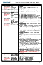
Page 33: ...eq is lower than the value and comes into under freq delay but still lower normal faults delay then under frequency alarms If the value is set as 0 then the alarm is disabled 9 Over voltage warning 0 200 120 Rated voltage multiplying by this value is regarded as over voltage alarm value When the voltage is higher than the value and comes into over voltage delay but still higher normal faults delay...

Page 34: ...ng to time setting 15 Gens unload continuous or pulse type according to time setting 16 E S T hold shutdown output it is used for gens with stop solenoid when the setting value of shutdown delay is over then it is off 17 Fuel pump output there is output if the oil capacity is lower than start condition for 10s and shutdown if it is higher than the shutdown condition for 1s 18 Mains loading continu...

Page 35: ...splay if setting as disable 2 Mains under volt 55 330V 184V When the mains voltage is lower than the low voltage crank threshold and comes into mains low voltage delay normal failure delay but still lower then mains becomes invalid If the voltage become higher than low voltage revert threshold during normal failure delay time then it will not alarm 3 Revert under volt 55 330V 207V 4 Mains over vol...

Page 36: ...ate timely 2 Current time 00 00 00 23 59 59 Permanent calendar inside please correct the time timely 3 Current week Monday Sunday Permanent calendar inside please correct the date timely 9 Self define curve NO Parameter Notes 1 Self define oil pressure resistance curve Sensor curve can be User defined by panel buttons resistance and according value should be input MAX 15 groups MIN 2 groups Rule r...

Page 37: ...rt Check fuel return circuit and wiring Check start battery Consult engine manual Starter motor does not respond Check the wiring to the starter Check start battery Unit operation but ATS does not switch Check the ATS Check the cable between the controller and the ATS USB communication is abnormal Check the USB connection Check whether the USB port of the computer is normal Check whether the USB d...

Reviews: