background image

"2047ES / 2647ES / 3247ES" Service & Parts Manual - CE Specifications

March 2008

Page 1-7

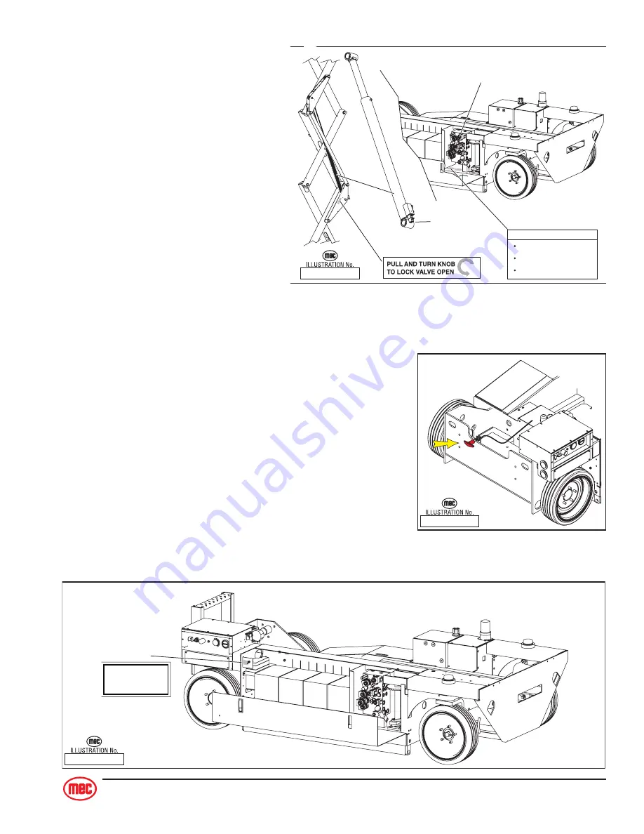
Emergency Lowering - 2047ES and 2647ES
(current models)

Emergency Down system is used to lower the platform in
case of power or valve failure. To lower the platform, pull the
red “T” handle located at the rear of the machine. Lowering
stops when you release the “T” handle.

Emergency Lowering - 3247ES (all models)

The Emergency Down System is used to lower the platform
in case of power or valve failure. To lower the platform, per-
form the following steps:

1. Push down on the toggle switch and hold it to lower

the platform to the desired height.

2. Once the platform is fully lowered, release the toggle switch to close the valve

ART_2172

2047ES / 2647ES

ART_2173

90918

EMERGENCY LOWERING

ACTUATE SWITCH  TO

LOWER PLATORM

90918

3247ES

ART_2249

EMERGENCY DOWN PROCEDURE

LOCK OPEN VALVE ON LIFT
CYLINDER ABOVE.

PULL MANUAL ACTIVATOR BELOW
TO LOWER PLATFORM.

TO RETURN TO NORMAL OPERATION
RESET LIFT CYLINDER VALVE.

90727

CYLINDER

VALVE

MANUAL

ACTIVATOR

8599

90727

8599

Emergency Lowering
- 2047ES and 2647ES
(early models)

The Emergency Down System is used
to lower the platform in case of power
or valve failure. To lower the platform,
perform the following steps:

1. Pull and turn knurled knob on

lift cylinder counterclockwise to
lock the valve in open position.

2. Pull manual activator (override

valve) on main manifold to
lower platform to
desired height.

3. To return to normal operation,

turn knurled knob on lift cylin-
der clockwise. Valve will automatically lock.

Summary of Contents for 2047ES

Page 1: ...CE SERVICE AND PARTS MANUAL Part 90972 R2 March 2008 2047ES 2647ES 3247ES Serial Number Range 2047ES 9801000 Present 2647ES 9901000 Present 3247ES 10001000 Present...

Page 2: ...1775 Park Street Suite 77 Selma CA 93662 USA Ph 1 800 387 4575 559 891 2488 Fax 559 891 2448 E mail info mecawp com Web www mecawp com Aerial Platform Sales Corp...

Page 3: ...III SECTION 1 HYDRAULIC SYSTEM 1 1 Hydraulic Fluid 1 2 Hydraulic System Components 1 4 Parking Brake and Towing Circuit 1 6 Emergency Systems And Procedures 1 6 Steering Circuit 1 8 Platform Lift Circ...

Page 4: ...ibration 3 8 CALIBRATION TROUBLESHOOTING Failure Messages 3 11 CALIBRATION TROUBLESHOOTING Information Messages 3 16 SECTION 4 MECHANICAL COMPONENTS 4 1 Torque Specifications 4 2 Mechanical Components...

Page 5: ...Controller Connections 5 17 Troubleshooting Battery Charger 5 19 SECTION 6 SCHEMATICS 6 1 Hydraulic Schematics 6 2 2047ES Serial 9801000 9801099 2647ES Serial 9901000 9901199 3247ES Serial 10001000 1...

Page 6: ...March 2008 2047ES 2647ES 3247ES Service Parts Manual CE Specifications Page iv Parts Manual SECTION A CONTROL BOXES SECTION B PLATFORM AND RAILS SECTION C SCISSORS SECTION D HYDRAULICS SECTION E BASE...

Page 7: ...1 SECTION 1 HYDRAULIC SYSTEM SECTION 1 HYDRAULIC SYSTEM 1 1 Hydraulic Fluid 1 2 Hydraulic System Components 1 4 Parking Brake and Towing Circuit 1 6 Emergency Systems And Procedures 1 6 Steering Circ...

Page 8: ...INJURY OR BLINDNESS FLUID LEAKS UNDER PRESSURE MAY NOT ALWAYS BE VISIBLE Fluid Recommendations MEC recommends the use of ISO Grade 32 hydraulic fluid A 150SSU EQUIVALENT substitute can be used if abso...

Page 9: ...om the hydraulic reservoir 8 Reinstall all hoses in the previous steps 9 Fill hydraulic reservoir with filtered fresh hydraulic fluid refer to Lubrication Chart 10 Loosen output hose fittings at pump...

Page 10: ...element must be changed every 6 months or 500 hours Extremely dirty conditions may require that the filter be replaced more often Beware of hot fluid Contact with hot fluid may cause burns Hydraulic P...

Page 11: ...2008 Page 1 5 ART_2171 Brake 2047ES 2647ES 3247ES Braking Circuit Rear brakes are released whenever the machine is commanded to drive ART_2165 Wheel Drive Circuit There are two 2 hydrau lic fixed dis...

Page 12: ...main manifold Using the hand pump on the manifold pump valve until pressure is built Machine is now ready for towing AFTER RELEASING THE BRAKES THERE IS NOTHING TO STOP THE MACHINE S TRAVEL MACHINE W...

Page 13: ...the toggle switch to close the valve ART_2172 2047ES 2647ES ART_2173 90918 EMERGENCY LOWERING ACTUATE SWITCH TO LOWER PLATORM 90918 3247ES ART_2249 EMERGENCY DOWN PROCEDURE LOCK OPEN VALVE ON LIFT CYL...

Page 14: ...ts Each wheel motor housings has a pivot and chain sprocket on the top A hydraulic steering cylinder is mechanically linked via tie rods to two 2 chain and sprocket assemblies one 1 for each motor hou...

Page 15: ...647ES One 1 single acting type hydraulic cylinder The cylinder has an integrated 2 position 2 way solenoid operated platform lower valve for hold ing the platform in position The valve is also externa...

Page 16: ...e Ended Cylinder Barrel Head Piston Securing Nut Rod Head Seals Seals Piston Vent to Tank Return to Tank Barrel Pressure Piston Securing Nut Typical Single Acting Cylinder Removal Note Refer to Sectio...

Page 17: ...he head and piston can be removed Be sure the shaft and vise are both clean before using 4 Remove nut at the end of the shaft and pull head and piston off of the rod 5 Remove all seals from the head a...

Page 18: ...arp seal tool 3 Place a small amount of fluid on the inside seals of the head and reinstall it on the shaft by slipping head over the piston end of the shaft being very careful not to damage the insid...

Page 19: ...remove built up contaminants then blow out all passages with clean compressed air 2 Inspect the manifold for cracks thread damage and scoring where O rings seal against internal and external surfaces...

Page 20: ...March 2008 2047ES 2647ES 3247ES Service Parts Manual CE Specifications Page 1 14...

Page 21: ...2008 Page 2 1 SECTION 2 ELECTRICAL SYSTEM SECTION 2 ELECTRICAL SYSTEM 2 1 Electrical System General 2 2 Deutsch Connectors 2 3 Batteries 2 4 Alarms and Switches 2 8 Continuity Checks 2 11 Diode Board...

Page 22: ...bled via the Base Platform Selector Switch disables the upper station and provides control for a fixed speed Lift UP DOWN functionality Upper Control box The upper station consists of a joystick contr...

Page 23: ...l tool or a wire hook to pull the locking wedge from the connector Replace worn or damaged parts Replace or re crimp wires and contacts Locking Fingers Remove the locking wedge as outlined above Using...

Page 24: ...wering circuit for the 3247ES Battery Maintenance in storage Follow these procedures for maintenance of battery on a machine not in use Keep battery clean Electrolyte of wet batteries should be checke...

Page 25: ...shortened battery life Excessive water usage can indicate that a battery has been overcharged has been subjected to excessively high temperatures or is nearing the end of its service life Battery Pre...

Page 26: ...AC input voltage range The charger will start automatically within four to six seconds The charger will start even with severely discharged batteries down to 1 volt terminal voltage Once charging star...

Page 27: ...batteries follow these procedures Batteries are located in the side compartment of the machine Always disconnect the negative battery cable first Remove bolts holding battery Lift the battery from the...

Page 28: ...n de pressed Turn button clockwise to reset NOTE As a safety feature selecting and operating the lower controls will override the upper controls emergency stop button The lower control box emergency s...

Page 29: ...The switch is used primarily to shut off control circuit The battery disconnect is provided to facilitate servicing and also to prevent unauthorized use of the ve hicle by using a padlock to provide...

Page 30: ...re safe machine operation Overload Pressure Switch The overload switch measures the pressure at the lift cylinder to calculate platform load The data is used by the load sensing system to prevent oper...

Page 31: ...er to nor mally open terminal With the switch flipped there should be a low resistance Check Emergency Stop Button Disconnect wires and connect one probe of ohm meter to connection on button and other...

Page 32: ...9 OUTPUT Brake Decel Valve signal 4 8 INPUT Steer Left 5 18 OUTPUT Steer signal to Sevcon 6 5 INPUT Down signal 7 20 OUTPUT Signal to Motion Alarm s optional 8 17 OUTPUT Sevcon Hour Meter motor functi...

Page 33: ...flash a code indicat ing the reason for the shutdown Refer to Section 5 Troubleshooting for diagnostic codes ART_2182 1 7 6 12 J5 Plug Pin Identification PIN WIRE FUNCTION 1 22 B power input power up...

Page 34: ...ion 9 No Connection 10 2 Platform Elevated indication B when platform stowed 11 15 Supply Negative connected to B 12 22 Supply Positive connected to B J3 P3 PIN WIRE FUNCTION 1 20 Base Alarm A8 2 6 Pl...

Page 35: ...VERLOAD SYSTEM SECTION 3 PLATFORM OVERLOAD SYSTEM 3 1 General Description 3 2 Electrical Connections 3 3 Troubleshooting 3 4 GP102 EZcal Help Messages 3 4 GP102 LED Flash Codes 3 7 Calibration 3 8 CAL...

Page 36: ...nt alarm are controlled by this system To access the control module for trouble shooting and calibration the EZcal hand held device is required These are available from MEC Aerial Platform Sales Corp...

Page 37: ...OAD LAMP output off normally turns on to indicate overload RED BLK 44 J P3 4 Cutout Relay output B when not overloaded BLK 15 J P3 5 Cutout Relay B internally linked to P2 11 J P3 6 no connect P4 J4 C...

Page 38: ...designed for use on 12V and 24V battery powered vehicles it cannot operate with a supply below about 9V The BATTERY voltage can be checked in the SENSORS menu available in the DIAGNOSTICS menu LED fla...

Page 39: ...ted until the problem is corrected LED flash code 9 INVALID LOAD CHECK SENSORS There is a problem which prevents the estimated load being determined there may be a fault with the height sensor or the...

Page 40: ...l vehicle operation will be prevented until the problem is corrected LED flash code 2 VEHICLE OVERLOADED The estimated load in the platform exceeds the OVERLOAD AT setting in the ADJUSTMENTS LOAD menu...

Page 41: ...he elevation switch on P2 10 If the height sensor has been adjusted or replaced repeat the CALIBRATE HEIGHT procedure LED flash code 5 This indicates a fault with the shutdown outputs of the GP102 a s...

Page 42: ...o TILT SETUPS Press Enter Display reads CALIBRATE LEVEL g Press Enter Display reads CALIBRATE LEVEL YES ENTER NO ESC h Press Enter Display reads TILT 0 0 0 0 i Press ESC ESC ESC j Disconnect EZcal fro...

Page 43: ...Esc Press Right Arrow to LOAD SETUPS Press Enter Display reads CALIBRATE LOAD j Press Enter Display reads PLATFORM DOWN Verify that platform is fully lowered k Press Enter Display reads PLATFORM LOADE...

Page 44: ...date using Up Down and Right Arrows Display reads FINISHED p Disconnect EZcal from the load sense control module The Platform Overload Sensing System is now calibrated Height Calibration The height s...

Page 45: ...of calibration The height sensor output must be between 1 0V and 4 0V Check DIAGNOSTICS SENSORS to see the output A reading of 0V or 5V is probably due to a wiring problem F06 CHECK ELEV This message...

Page 46: ...of range during the DYNAMIC lift The height sensor output must be between 1 0V and 4 0V Check DIAGNOSTICS SENSORS to see the output A reading of 0V or 5V is probably due to a wiring problem F15 CHECK...

Page 47: ...raised Check DIAGNOSTICS SYSTEM to check the height F24 TOO MANY This message occurs if too many static measurements are taken during a calibration step In the rare event that this occurs please call...

Page 48: ...e is unacceptable There is not enough difference between the initial pressure peak and the minimum pressure Check the pressure sensor and lift cylinder hydraulics F40 REJECT DELTA This message indicat...

Page 49: ...other wiring error Check DIAGNOSTICS SENSORS to check the pressure F45 HIGH PRESSURE This message indicates that the pressure is too high 4 5V or more at a STATIC measurement point This message would...

Page 50: ...s released during either STATIC lowering phase when more measurements are needed before the platform is fully lowered GO UP MORE This message occurs if the UP switch is released during either STATIC l...

Page 51: ...essage is prompting for confirmation that the platform is completely empty Press ENTER to confirm when the platform is empty PLATFORM LOADED This message is prompting for confirmation that the platfor...

Page 52: ...is necessary to redo the EMPTY phase If the previous EMPTY calibration was in error or if the pressure sensor is replaced it will be necessary to redo the EMPTY phase REDO LOADED This message is displ...

Page 53: ...AL COMPONENTS 4 1 Torque Specifications 4 2 Mechanical Components 4 3 Base Undercarriage 4 3 Hoses and Cables 4 3 Raising the Machine 4 4 Tires Wheels 4 5 Front Drive Motors 4 6 Rear Wheel Brakes 4 7...

Page 54: ...10 X 1 50 M12 X 1 75 M14 X 2 00 M16 X 2 50 M18 X 2 50 M20 X 2 50 M22 X 2 50 M24 X 3 00 M27 X 3 00 M3 X 3 00 6 16 29 52 85 130 172 247 332 423 637 872 8 20 35 62 103 158 210 301 404 517 779 1066 8 21 5...

Page 55: ...brackets Check for cylinder pins that turn in their mounting which will indicate sheared retaining pins Hoses and Cables Note Refer to Parts Section E for detailed hydraulic hose diagrams Inspect all...

Page 56: ...raise the machine 1 Move machine to a firm level surface capable of supporting the weight of the machine 2 Chock tires on one end of machine and raise the other end of machine 3 Position a jack at th...

Page 57: ...n the rating of this equipment Changing Tires Wheels ALWAYS BLOCK THE MACHINE BEFORE RAISING THE MACHINE When a tire wheel change is necessary follow these tips 1 While the machine is on the ground lo...

Page 58: ...nd tire assembly to access drive motor 4 Disconnect the Steering Linkage refer to illustration 5 Remove the steering stop refer to illustration 6 Remove the cotter key motor shaft nut and hub from the...

Page 59: ...ect hose assemblies from the brake 4 Remove the relief valve 5 Remove the cap screws and remove the brake from the housing Replace Installation is reverse of removal ART_2188 TORQUE Ft lbs Nm Lug Nuts...

Page 60: ...d support the front end of machine see Raising the Machine 2 Disconnect hydraulic hoses and cap them 3 Remove the bolts holding the steering cylinder to the steering links and move the steering links...

Page 61: ...ion rails Repair 1 Raise the scissor arm assembly and support using the maintenance lock 2 Refer to the illustration and Parts Section E ART_2191 REAR BULKHEAD ON BASE WELDMENT Depression Rail Pivot A...

Page 62: ...s Remove any compo nents that will obstruct the scissor slide path 4 Remove the bolts from both fixed blocks at the rear of the platform 5 Lift the rear of the platform until the fixed blocks are clea...

Page 63: ...s 4 Use a suitable lifting device to support the lift cylinder CAUTION Attach the lifting device to the cylinder body Lifting by the rod end will cause the cylinder to extend 5 Remove the upper retain...

Page 64: ...scissor is clear and remove the limit speed cam 5 Slide the scissor assembly to the rear until the slide block reaches the end of slide chan nel and lift the scissor assembly CAUTION The scissor assem...

Page 65: ...HOOTING SECTION 5 TROUBLESHOOTING 5 1 General Troubleshooting Tips 5 2 Hydraulic Pressure Adjustment Procedures 5 4 Troubleshooting 5 6 Sevcon Motor Speed Controller 5 14 LED Diagnostics Definitions F...

Page 66: ...tery connections are secure and battery is fully charged Check that the emergency stop button is released UP OUT position Check that the hydraulic fluid is at the correct level Check that the brake re...

Page 67: ...2047ES 2647ES LOWER LIFT CYLINDER 3247ES UPPER LIFT CYLINDER 3247ES G E E F F D C C I I H J J M M N N O O K K L L A A B B R R MAIN MANIFOLD Early Models MAIN MANIFOLD Current Models HP1 TEST PORT TES...

Page 68: ...em Disconnect forward or reverse coil of drive valve Energize drive function by moving joystick lever in the direction of the already disconnected coil Hold the switch for 10 seconds to get an accurat...

Page 69: ...unterbalance If adjustment is required set pressure to the correct setting as follows Open the freewheel valve NV1 completely Operate drive in either direction Hold the switch for 10 seconds to get an...

Page 70: ...ting flash codes Functions from lower controls but not from upper controls Upper Emergency Stop switch pushed in Pull upper emergency stop switch Interlock switch joystick Check power to red wire powe...

Page 71: ...tion Check wire 10 through plug connections from upper control box to Diode Board Failed diode in diode board Test diodes on diode board replace diode board 3247ES only E down battery discharged shoul...

Page 72: ...p motor runs while attempting to drive HIGH pressure indicated at Test Port TP 1 Counterbalance Valve CBV1 failure Replace CBV1 Drive valve SV3 not shifting Check power to SV3 Remove SV3 and check for...

Page 73: ...itch S8 inoperative Check operation of micro switch Located in upper control box on joystick Mode Selector Switch S6 faulty Check power through S6 on wire 11 Damaged wiring or poor plug connection Che...

Page 74: ...Counterbalance Valves in this section Replace valve No Steer Either direction Pump motor OPERATES while attempting to steer Steer valve SV1 not shifting Check power to SV1 remove SV1 and check for con...

Page 75: ...tor OPERATES while attempting to steer Steer valve SV1 not shifting Check power to SV1 Remove SV1 and check for contamination Replace SV1 Steering linkage binding Inspect lube linkage replace as neces...

Page 76: ...t Drive Selector Switch 2 Emergency Stop Switch 3 Torque Switch 4 Overload Warning Light Red 5 Horn Button option 6 Steering Micro Switches 7 Drive Enable Switch 8 Reverse Down Rocker Switch 9 Forward...

Page 77: ...l 8 17 OUTPUT Sevcon Hour Meter motor function requested 9 15 INPUT Battery Negative 10 7 INPUT Steer Right 11 4 INPUT Lift Up 12 2 INPUT Limit Switch 24V platform down 13 3 OUTPUT Enable from lower L...

Page 78: ...e shutdown Refer to the LED Diagnostics Definitions and Sevcon Motor Speed Controller Connections on the following pages ART_2182 1 7 6 12 J5 Plug Pin Identification PIN WIRE FUNCTION 1 22 B power inp...

Page 79: ...it at rest and is the result of the voltage at M 2 dropping to approximately 4 volts or lower Possible causes Short to ground in the motor circuit between the motor contactor and the M 2 terminal Moto...

Page 80: ...electric motor will still run Accelerator fault Set with unit at rest a 6 flash will result in an 80 cutback of motor speed The Accelerator is the proportional control circuitry for the Sevcon It work...

Page 81: ...Battery Positive Input Switched 5 less than battery voltage Controller begins the motor run sequence with this signal but still requires a signal on pin 4 and a change on pin 9 before the motor will o...

Page 82: ...er control box From 3 5 V DC with joystick in the neutral to 0 V DC at full stroke Controller uses this circuit to monitor joystick input after pins 2 4 energize Controls motor speed in reference to t...

Page 83: ...E THE CHARGER IF IT IS MALFUNCTIONING PERSONAL INJURY OR PROPERTY DAMAGE MAY RESULT Incorrect assembly may result in a risk of electric shock or fire The following procedures are intended only to dete...

Page 84: ...2185 Please see service manual for additional information 100 charged 75 to 100 charged 50 to 75 charged 0 to 50 charged ON ON ON 50 Blinking ON ON Blinking OFF ON Blinking OFF OFF 75 100 BATTERY CHAR...

Page 85: ...taneously Output connection error Check the AC input voltage The charger is indicating the AC voltage is too low or too high This is an unusual problem and would most likely occur with a very poorly r...

Page 86: ...blem If the AC supply checks good the charger should be replaced The AC line circuit breaker or fuse is blown A defective circuit breaker or fuse overloaded circuit or a charger problem can cause this...

Page 87: ...9 2647ES Serial 9901000 9901199 3247ES Serial 10001000 10001199 6 2 2047ES Serial 9801100 CURRENT 2647ES Serial 9901200 CURRENT 3247ES Serial 10001200 CURRENT 6 4 Electric Schematics 6 9 2047ES Serial...

Page 88: ...alve Lower Lift Cylinder Manifold MA 4 3247ES only ORF5 Orifice Down Valve Upper Lift Cylinder Manifold MA 5 3247ES only P1 Pump Pump Compartment PCF1 Steering Relief Flow Control Main Manifold MA 1 R...

Page 89: ...E RIGHT WHEEL MOTOR PORT A PORT B 8 9 LEFT WHEEL MOTOR PORT B PORT A 10 11 12 2 3 1 4 5 6 7 2100 PSI 2047 2647 1900 PSI 3247 2047 2647 ONLY 2750 PSI 1500 PSI 1 0 GPM 850 PSI 5 PSI R I H E F G J P L N...

Page 90: ...Orifice Disc Brake Release Main manifold MA 1 ORF3 Orifice Down Valve Lift Cylinder Manifold MA 3 2047ES and 2647ES only ORF4 Orifice Down Valve Lower Lift Cylinder Manifold MA 4 3247ES only ORF5 Ori...

Page 91: ...3 MA 5 MA 4 LIFT CYLINDER 2047ES 2647ES LOWER LIFT CYLINDER 3247ES UPPER LIFT CYLINDER 3247ES STEERING CYLINDER BRAKES LEFT WHEEL MOTOR RIGHT WHEEL MOTOR S1 S3 S2 S4 SV9 WB1 WB2 WM1 WM2 SV1 FRR1 SV2 P...

Page 92: ...SV2 Lift SOL5 Coil SV4 Torque SOL6 Coil SV6 Torque SOL7 Coil SV3 Drive Forward SOL8 Coil SV3 Drive Reverse SOL9 Coli SV7 Brakes SOL10 Coil SV8 Down FD1 Flow Divider MP1 Manual Pump Brake Release NV1 N...

Page 93: ...V3 Drive Forward SOL8 Coil SV3 Drive Reverse FD1 Flow Divider FRR1 Flow Control Steer Relief HP1 Hand Pump Brake Pump MP1 Manual Pump Brake Release NV1 Needle Valve Freewheel ORF1 Orifice Plug Flow Re...

Page 94: ...March 2008 2047ES 2647ES 3247ES Service Parts Manual CE Specifications Page 6 8 THIS PAGE INTENTIONALLY LEFT BLANK...

Page 95: ...S2 UP DOWN makes contact from the CENTER to the LEFT position when the switch is held in the CONTACT position and automatically returns to the CENTER position when released 3 Switch LS1 breaks the N C...

Page 96: ...nable Drive and High Speed Right Rear Corner of Machine LS2 Limit Switch Single Pole Drive Enable if Pothole Deployed On pothole Linkage LS3 Limit Switch Single Pole Enable Drive if Pothole Deployed O...

Page 97: ...2 P1 3 P1 4 P1 5 P1 6 P1 7 P3 7 P3 8 P3 1 P12 2 P3 6 P5 12 P12 1 P3 5 P5 11 P5 1 CB1 CIRCUIT BREAKER OPTIONAL BATTERY GAUGE CHRL 1 P3 4 LS2 LS1 MOTOR CONTROLLER PWM J 5 MC1 F1 CH1 P3 15 P1 8 P1 9 P1...

Page 98: ...ompartment 3247ES ONLY LS1 Limit Switch Double Pole Enable Drive and High Speed Right Rear Corner of Machine LS2 Limit Switch Single Pole Drive Enable if Pothole Deployed On pothole Linkage LS3 Limit...

Page 99: ...SV1 STEER DRIVE SV3 LS1 J2 J3 J4 RL1 LOAD SENSE SYSTEM GP 102 P9 1 LIFT MOTOR CONTROLLER PWM J 5 MC1 F1 CH1 RIGHT LEFT BRAKE DECEL MAIN MANIFOLD TORQUE TORQUE REV FWD P9 2 P3 15 P1 8 P1 9 P1 10 P1 11...

Page 100: ...12 H 10 P 11 U 3 T 6 J 7 N 2 C 8 K 14 M 16 GND REMOVABLE CONTROL HARNESS END VIEW OF REMOVABLE CONTROL HARNESS OPTIONAL QUICK DISCONNECT TERMINAL BLOCK ON UNDERSIDE OF PLATFORM DECK L 15 CB1 ES1 S1 S2...

Page 101: ...fications March 2008 Page 6 15 2471 none Component Locations 2047ES 2647ES 3247ES all CE Model Serial Publication Art Reference Art _ _ REFER TO ELECTRIC SCHEMATIC B5 F2 D19 ED1 3247 ONLY UPPER LIFT C...

Page 102: ...SOL2 SOL5 SOL3 SOL6 SOL8 SOL7 STEER LEFT SOL2 STEER LEFT TORQUE SOL5 TORQUE LIFT SOL9 LIFT SOL4 BRAKE SOL10 DOWN TORQUE SOL6 TORQUE DRIVE FORWARD REVERSE SOL8 SOL7 DRIVE FORWARD REVERSE DECEL SOL3 DE...

Page 103: ...s to Potentiometer 10 none none 11 none none 12 none none Terminal Identification POST FUNCTION B Battery Positive Cable from 200 AMP Fuse B Negative Battery Cable and GROUND wire 15 connection M2 Mot...

Page 104: ...Connection 2 No Connection 3 4 P6 1 4 5 P6 2 5 No Connection 6 No Connection 7 20A P6 3 8 No Connection 9 No Connection 10 2 P6 4 11 15 P6 5 12 22 P6 6 J3 P3 PIN WIRE CONNECTION 1 20 Motion Alarm A8 2...

Reviews: