background image

Page 155

Speed Level Seres - Servce & Parts Manual

January 2019

Secton 9 - Troubleshootng - 3084ES Models

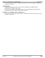
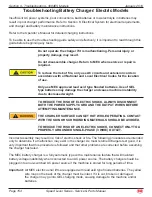
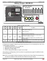
Battery Charger, HB1500-48

ART_2374

ALL LED’S MUST BE OFF BEFORE
CONNECTING TO AC POWER

INDUSTRIAL

BATTERY CHARGER

FAULT

STATUS

HSB1500-48

AUTO SELECTABLE DUAL AC INPUT
100 - 240V ~ 50/60 Hz  18A

48V

25A

Please see service manual for additional information.

Normal, battery is 100% charged

Normal, battery is over 80% charged

Normal operation, charger is charging

No AC power to charger

OFF

ON

ON

YELLOW

OFF

OFF

ON

OFF

OFF

ON

OFF

OFF

OFF

80%

100%

FAULT

BATTERY CHARGER

INDICATOR

OFF

OFF

OFF

OFF

STATUS

80% 100%

FAULT

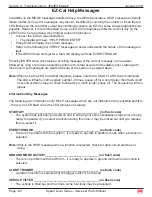
Battery Charger Fault Codes

CHG 

YELLOW 

LED

80% 

GREEN 

LED

100% 

GREEN 

LED

Fault RED 

LED

Condition

X

X

X

ON

Battery pack probably bad

Weak or bad cell

Batteries excessively discharged

OFF

OFF

OFF

ONE 

FLASH

Output open circuit or short circuit or reverse polarity 
connection of battery to charger

Battery voltage is too high (may be connected to wrong 
voltage battery)

OFF

OFF

OFF

TWO 

FLASH

Charger has timed-out at 22 hours (battery pack probably 
bad or bad cell)

X = “don’t care”

 LED may be ON or OFF

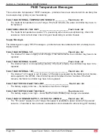
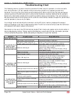
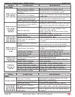
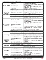
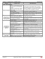
To determine if a charger is malfunctioning, identify the problem from the following list and refer to the 
Trouble Table for instructions.

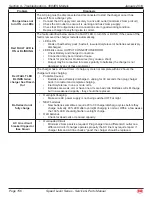
Charger does not turn ON -or- no yellow LED
Red FAULT LED is ON or BLINKING
Batteries do not fully charge
The AC supply circuit breaker is tripped or fuse is blown

If the problem is not listed above, refer the problem to a qualified service agent for additional trouble 
shooting procedures.

Note:

Over 1/2 of all battery chargers returned as “failed” are good. Please follow the troubleshooting 
procedures carefully and check all other items before returning the charger.

1.
2.
3.
4.

Summary of Contents for 2684ES

Page 1: ...85 R1 January 2019 Speed Level Series RT Internal Combustion ES Electric 2684ES Serial Number Range 12700000 Up 2684RT Serial Number Range 12800000 Up 3084ES Serial Number Range 11700000 Up 3084RT Ser...

Page 2: ...ary 2019 Revision History Date Reason for Update January 2019 Speed Level Mk 2 Update 1401 S Madera Avenue Kerman CA 93630 USA Toll Free 1 877 632 5438 Phone 1 559 842 1500 Fax 1 559 842 1520 info MEC...

Page 3: ...tandard 11 Hydraulic Components Torque Table 12 Emergency Systems And Procedures 13 Parking Brake And Towing Circuit 14 Lift And Support The Machine 15 Transporting The Machine 16 Section 5 Hydraulic...

Page 4: ...s 87 General Troubleshooting Tips 87 Electrical System Troubleshooting 3084RT 88 GP400 Module 89 Matrix Module Terminal Block Module TBM 90 EZ Cal Scan Tool 91 Using The EZ Cal With The Flow Charts 92...

Page 5: ...Dual Fuel Lower Control Box Electric Schematic 168 3084RT Dual Fuel Base Electric Schematic 169 3084RT Diesel Lower Control Box Electric Schematic 170 3084RT Diesel Base Electric Schematic 171 3084RT...

Page 6: ...otor Front 231 Section 15 Hydraulics 233 Main Manifold Assembly Electric Models Part 1 233 Main Manifold Assembly Electric Models Part 2 235 Main Manifold Assembly RT Models Part 1 237 Main Manifold A...

Page 7: ...309 Decals ES Models ANSI Specification Part 1 309 Decals ES Models ANSI Specification Part 2 311 Decals ES Models ANSI Specification Part 3 313 Decals ES Models ANSI Specification Part 4 314 Decals R...

Page 8: ...ng and ordering the correct replacement parts All parts represented here are manufactured and supplied in accordance with MEC quality standards We recommend that you use genuine MEC parts to ensure pr...

Page 9: ...res demonstrate our commitment to Quality and our relentless ongoing efforts towards Continuous Improvement due to which product specifications are subject to change without notice Any procedures not...

Page 10: ...stant maintenance is the key to efficient economical operation of your aerial work platform It will help to assure that your equipment will perform satisfactorily with a minimum of service and repair...

Page 11: ...portional Drive Speed Platform Elevated 0 4 mph 0 6 km h Drive Speed Platform Lowered 0 3 2 mph 0 5 km h Lift Lower Speeds Approximate 35 sec 40 sec Gradeability 40 22 Ground Pressure Wheel Maximum 90...

Page 12: ...eed Platform Elevated 0 4 mph 0 6 km h Drive Speed Platform Lowered 0 3 2 mph 0 5 km h Lift Lower Speeds Approximate 35 sec 40 sec Gradeability 40 22 Ground Pressure Wheel Maximum 98 psi 6 9 kg cm2 10...

Page 13: ...lic components or hoses open They must be protected from contamination including rain at all times Never open a hydraulic system when there are contaminants in the air Always clean the surrounding are...

Page 14: ...positive side of the battery and a metal surface on the machine This can cause damage to the electrical system battery explosion and personal injury Total System Engine coolant level must be checked o...

Page 15: ...8 43 Document Box Ladder Boom Support Wheel Lift Cylinder Upper Controls Pivot Gear Tilt Cylinder Front to Rear Upper Boom Control Module Lower Controls Propane Tank Dual Fuel Models Platform and Rail...

Page 16: ...minal Block Module GP400 Module 12 Volt DC Battery Emergency Lowering Switch Lower Controls Hydraulic Reservoir Overflow Reservoir Radiator Fuel Reservoir Hydraulic Fluid Filter Engine Air Intake Engi...

Page 17: ...45 55 5 61 7 16 14 41 45 55 5 61 55 60 74 5 81 7 16 20 51 55 69 74 5 68 75 92 102 1 2 13 65 72 88 97 5 86 96 116 130 1 2 20 76 84 103 114 102 112 138 152 9 16 12 95 105 129 142 127 140 172 190 9 16 18...

Page 18: ...31 36 5 M10 1 50 29 35 39 47 42 52 57 70 M12 1 75 52 62 70 84 75 91 102 123 M14 2 00 85 103 115 139 120 146 163 198 M16 2 50 130 158 176 214 176 216 238 293 M18 2 50 172 210 233 284 240 294 325 398 M...

Page 19: ...on the Hydraulic Components Torque Table Parts drawings and service instructions in this manual Packaging and instruction sheets provided with new parts Instruction manuals provided by the manufactur...

Page 20: ...top all machine functions Both switches must be reset or machine will not operate Selector Switch Is Set To Base The upper controls are locked out The lower controls switch must be reset or the machin...

Page 21: ...S NOTHING TO STOP THE MACHINE S TRAVEL MACHINE WILL ROLL FREELY ON SLOPES BE ON GUARD AGAINST RUNAWAY Prior to manually releasing brakes insure wheels are chocked to prevent unintentional movement Dis...

Page 22: ...chine to a firm level surface capable of supporting the weight of the machine Chock tires on one end of machine and raise the other end of machine If wheel is to be removed break loose but do not remo...

Page 23: ...E MEC MACHINERY DRIVERS ARE ALSO RESPONSIBLE FOR SELECTING THE CORRECT AND APPROPRIATE TRAILER ACCORDING TO GOVERNMENT REGULATIONS AND COMPANY POLICY DRIVERS MUST ENSURE THAT THE VEHICLE AND CHAINS AR...

Page 24: ...iston type pump which is directly coupled to the engine As the engine turns the hydraulic pump drains fluid from the reservoir and pumps this fluid to the valve manifold If no function is selected to...

Page 25: ...2 front and two 2 rear The two rear wheel motors have integral spring held brakes The brakes are released by hydraulic pressure developed in the drive circuit during drive mode A fixed orifice in the...

Page 26: ...h platform fully down drain hydraulic fluid from hydraulic reservoir into a clean empty container When the hydraulic reservoir is empty remove suction strainer and hoses Remove the bypass filter and h...

Page 27: ...n the filter is clogged hydraulic flow bypasses the filter element The filter element must be changed every six 6 months or 500 hours Extremely dirty conditions may require that the filter be replaced...

Page 28: ...bolts that hold the pump to the housing Remove the pump Install Install drive hub onto pump shaft Torque bolt to 45 Ft Lbs 61 Nm Position the pump next to the housing Turn the pump until the splines o...

Page 29: ...Check the surface of the shaft and the housing for imperfections Install new shaft seal Cover the keyway portion of the drive shaft with tape to prevent damage to the seal during installation Coat the...

Page 30: ...e Adjustment Line Sense Port Pressure Port Suction Port Main Pressure Adjustment Minimum Flow Adjustment Case Drain Port Piston Piston Spring Control Piston Guide Shim Shim Rotary Group Control Piston...

Page 31: ...Hydraulic Pump 3084ES The hydraulic pump and electric motor used on the 3084ES model contain no serviceable parts and must be replaced rather than repaired See the Parts Manual for more information AR...

Page 32: ...h clean compressed air Inspect the manifold for cracks thread damage and scoring where O rings seal against internal and external surfaces Wash and dry each component and check for thread damage torn...

Page 33: ...ELIEF RV1 STEER RELIEF RV2 PRESSURE PORT TO PUMP RIGHT REAR A LEFT REAR B STEER LEFT 108 GRN RED COUNTERBALANCE VALVES BACK FRONT Hydraulic Manifold 3084RT ART_3147 RIGHT SIDE LEFT SIDE DRIVE FORWARD...

Page 34: ...IGH TORQUE 313 YEL BLK HAND PUMP BRAKE RELEASE STEER RIGHT 107 ORG WHT HIGH SPEED 213 YEL WHT TO TANK ORLS LINE SENSE RIGHT FRONT A LEFT FRONT B RIGHT REAR B LEFT REAR A LEFT FRONT A ORR GLS BRAKE POR...

Page 35: ...ection 5 Hydraulic System ART_3176 TILT FRONT TO REAR B CHECK VALVE TILT FRONT TO REAR A ORS MAIN MANIFOLD AXLE LOCK CYLINDERS ORIFICE PLUG T MAIN MANIFOLD ORLS MAIN MANIFOLD TILT SIDE TO SIDE A ORIFI...

Page 36: ...ackup ring from the bearing to service the motor Remove the high pressure seal from the groove in the pilot of the housing Discard shaft seal backup seal and high pressure seal Clean all parts in an o...

Page 37: ...sembly Apply a light coating of fluid to all new seals prior to installation Install the drive link into the end of the shaft with the tapered end facing up Place the rear housing seal in the groove i...

Page 38: ...ng 15 Thrust Washers 2 16 Thrust Bearing 17 Housing 18 Rear Housing Bearing 19 Drive Link 20 Divider Plate 21 Rotor Assembly 22 Manifold 23 Commutator Assembly 24 Endcover Piston 25 Piston Spring 26 E...

Page 39: ...allation Place the housing on a clean flat surface with the output end facing up Install the dust seal with the lip on the seal facing up Clamp the housing in a vise with the pilot on the housing faci...

Page 40: ...onto the housing with the side of the rotor with the chamfer in the splines facing the housing Place the manifold over the rotor with the seal groove side up Install the manifold seal Install the com...

Page 41: ...s 2 20 Piston 21 Springs 25 22 Spacer Shims 1 3 23 Rear Housing 24 Capscrews 8 25 Drive Link Spacer 26 Drive Link 27 Rotor Assembly 28 Manifold 29 Commutator Assembly 30 Endcover Piston 31 Piston Spri...

Page 42: ...Refer to the Parts Manual Section 15 for parts list There are two 2 cylinders in the floating axle system These cylinders allow fluid to transfer from one side to the other while the platform is in th...

Page 43: ...ogether via a tie rod Steering is accomplished hydraulically by using two 2 double acting cylinders and a 4 way 3 position solenoid operated hydraulic directional control cartridge valve Maximum steer...

Page 44: ...cylinders work in conjunction with a pivot mount to allow the platform and boom to tilt front to rear and side to side in order to provide a level work platform Automatic leveling is controlled by the...

Page 45: ...or to obtain proportional lifting function controlled by the lift valve Lowering is single speed When lowering the holding valve on the lift cylinder opens allowing gravity to lower the platform Lower...

Page 46: ...platform lower valve for holding the platform in position The valve is also electrically actuated via a toggle switch for manually lowering the platform The normally closed holding valve prevents retr...

Page 47: ...for Remove and Replace instructions and the Parts Manual for a list of hardware specific to the cylinder being repaired Tag hoses for proper reassembly Disconnect hoses and IMMEDIATELY cap the openin...

Page 48: ...t After installing seals wait at least one hour before assembling the cylinder to allow the seals to return to their original shape Torque all hardware according to the Hydraulic Components Torque Tab...

Page 49: ...available only on model 3084RT ART_3150 R1 9184 3 AU TO LEVE L MA NU AL LEVE L HOL D SWI TCH UNT IL LEV ELIN G IS COM PLE TE HOL D SWI TCH IN DES IRED DIRE CTIO N Fron t to Rea r Side to Side Control...

Page 50: ...ols joystick Emergency Stop There are two red Emergency Stop switches One located on the upper controls and one on the lower controls Activation of either Emergency Stop switch will immediately cut el...

Page 51: ...achine is equipped with a start system protective device controlled by the GP400 This protects the starter and related parts from damage caused by overcranking in hard starting situations Maximum star...

Page 52: ...d operate the electrical circuits 3084ES Eight 8 batteries 6 Volts DC supply power required to operate the machine Battery Maintenance In Storage Follow these procedures for maintenance of battery on...

Page 53: ...age can indicate that a battery has been overcharged has been subjected to excessively high temperatures or is nearing the end of its service life Battery Preventative Maintenance Every 15 hours after...

Page 54: ...em Always disconnect the negative battery cable first Always connect the positive battery cable first To Remove A Battery Turn the Battery Disconnect switch to OFF Disconnect the battery cables and re...

Page 55: ...e activation is automatic 3 Lower Button Press and hold to lower the platform Release to stop lowering 4 Emergency Stop Switch Press to stop all machine functions Turn clockwise to reset 5 Hour Meter...

Page 56: ...from either control panel 2 Raise Button Press and hold to elevate the platform Release to stop elevation Throttle activation is automatic 3 Lower Button Press and hold to lower the platform Release t...

Page 57: ...t be turned OFF before attempting to start 6 Tilt Indicator Light Light ON indicates platform out of level Platform will not elevate when TILT light is ON 7 Speed Torque Switch High Torque Slow speed...

Page 58: ...orm out of level Platform will not elevate when TILT light is ON 6 Speed Torque Switch High Torque Slow speed Provides maximum torque for rough terrain and climbing Mid Range Mid speed Provides medium...

Page 59: ...sor The Angle Sensor provides platform elevation information to the GP400 control module When the GP400 reads a certain output from the angle sensor it will Disable tilt operation Enable tilt sensor c...

Page 60: ...ar the steer cylinder mount Provides axle position information to the GP400 through the CAN bus system ART_3224 Relays 3084RT Only Relays are located on the engine inside the power module These relays...

Page 61: ...oval tool or a wire hook to pull the locking wedge from the connector Replace worn or damaged parts Replace or re crimp wires and contacts Locking Fingers Remove the locking wedge as outlined above Us...

Page 62: ...Pole 2 Position Disconnect wires Connect first probe of ohm meter to common terminal Connect second probe to top normally open terminal With toggle DOWN there should be no reading With the toggle UP t...

Page 63: ...ommon Normally Open Normally Open Normally Open Normally Open Common Normally Open Normally Open Common ART_2564 Momentary Button Switch Disconnect wires Connect one probe of ohm meter each terminal W...

Page 64: ...ocessor is located in the lower control box The GP400 Matrix Module is located in the upper control box Diagnostic information can be found in Section 9 or 10 for Troubleshooting Wiring information ca...

Page 65: ...quires replacement a calibration process must be performed before the machine can be operated The GP400 will operate initially in an assembly mode to provide basic machine operation However it will di...

Page 66: ...ly height calibration CE calibration is required of all machines outfitted with an Overload Protection System as required for CE certification All steps in the CE calibration must be performed in the...

Page 67: ...ith the cursor flashing Press the Up and Right arrows to enter code 2222 Press Enter Display reads ACCESS LEVEL 2 On later models the display may continue to read ACCESS LEVEL 3 Repeat step b and ente...

Page 68: ...measurements are taken LOADED calibration fully loaded platform raised lowered with stops to take measurements STATIC measurements are taken EMPTY calibration unloaded platform raised lowered with sto...

Page 69: ...in the up position until machine is fully elevated then release switch Display reads TOTAL DATA XX then PLEASE LOWER Note The platform will rise incrementally during this phase on the calibration Do n...

Page 70: ...ess Up and Right Arrow to enter code 2222 Press Enter Display reads ACCESS LEVEL 2 On later models the display may continue to read ACCESS LEVEL 3 Repeat step b and enter code 1775 Press Right Arrow t...

Page 71: ...out of range at the start of calibration The height sensor output must be between 1 0V and 4 0V Check DIAGNOSTICS SENSORS to see the output A reading of 0V or 5V is probably due to a wiring problem F0...

Page 72: ...een 1 0V and 4 0V Check DIAGNOSTICS SENSORS to see the output A reading of 0V or 5V is probably due to a wiring problem F15 CHECK ELEV This message is given if the elevation switch P7 5 is open when t...

Page 73: ...switch is either staying closed to a higher height or staying open to a lower height than that recorded during the DYNAMIC phase F27 BAD HEIGHT This message indicates a problem with the height sensor...

Page 74: ...height at which there was insufficient difference and the Up and Down values show the loaded pressure first and the difference between loaded and empty pressure second F42 LOW PRESSURE This message in...

Page 75: ...output must be between 0 5V and 4 5V Check DIAGNOSTICS SENSORS to see the output A reading of 0V or 5V is probably due to a wiring problem F52 NOT CALIBRATED This message is a catch all code which in...

Page 76: ...urs if the DOWN switch is released during either STATIC lowering phase when more measurements are needed before the platform is fully lowered GO UP MORE This message occurs if the UP switch is release...

Page 77: ...firm when the platform is empty PLATFORM LOADED This message is prompting for confirmation that the platform is loaded to rated load 1500 lbs US CSA 680 Kgs CE AU 100 of the load rating listed on the...

Page 78: ...Y phase REDO LOADED This message is displayed if the LOADED phase of load calibration has previously been completed Press ENTER when NO is displayed if there is no need to redo the LOADED phase Press...

Page 79: ...THE RATING OF THE EQUIPMENT IF FOAM FILLED TIRES WERE FITTED AS ORIGINAL EQUIPMENT THEY MUST BE REPLACED WITH EQUIVALENT SPECIFICATION TIRES AND FOAM FILL WEIGHT Changing Tires Refer to Lift and Supp...

Page 80: ...ART_3164 Remove Raise and support the front end of machine Remove the wheel and tire assembly to access drive motor Remove the hub from the drive motor shaft using a suitable hub pulling tool DO NOT u...

Page 81: ...hose guards Disconnect hose assemblies from drive motor Immediately cap and plug all openings to prevent contamination Remove the hose fitting and the bypass valve solenoid from the motor Remove the...

Page 82: ...front end of machine see Raising the Machine Disconnect hydraulic hoses Immediately cap and plug all openings to prevent contamination Remove the nut and bolt holding the steer cylinder to the motor m...

Page 83: ...and remove the pivot pin Replace Installation is reverse of removal Apply one 1 drop of Loctite to the bolts that secure clevis pins Bleed Procedure 3084RT Use this procedure for machine model 3084RT...

Page 84: ...in Platform Leveling Cylinders There are two Tilt Cylinders located at the rear of the machine NEVER PERFORM SERVICE ON THE MACHINE WITH THE PLATFORM ELEVATED WITHOUT FIRST SUPPORTING THE PLATFORM BOO...

Page 85: ...ce to the platform Disconnect cables that go to the platform Remove the bolts that secure the platform to the boom assembly Lift the platform away from the boom assembly Installation is reverse of rem...

Page 86: ...n on the boom assembly While supporting the cylinder carefully remove the mounting pin and lower the cylinder to the chassis Remove the bolt lock washer and banjo pin from the lower mounting pin then...

Page 87: ...pin Lift the upper tension beam up and away Remove boom pivot Attach a crane to the boom pivot through the top holes and apply enough lift to provide support While supporting the tension beam remove t...

Page 88: ...ever occurs first Severe Conditions Change every three months or 300 hours whichever occurs first 3 Tilt Cylinders Pivot Points Lithium N L G 2 EP Purge old grease Scheduled Maintenance Normal Conditi...

Page 89: ...plug Remove the old filter and wipe the filter seal contact surface with a clean towel Coat the seal on the new filter with clean oil then install and tighten by hand Fill engine with 10w 30 motor oil...

Page 90: ...rator Valve at the bottom of the fuel cartridge to drain water 1 2 3 4 5 6 Hand Lever Fuel Injector Bleed Screw Fuel Injector Pump Fuel Filter Bleed Screw Lift Pump Fuel Filter Housing Fuel Filter Car...

Page 91: ...te The solenoid must retract and extend smoothly If movement is impaired it may be necessary to reposition the solenoid to improvement alignment With the solenoid piston fully retracted measure the di...

Page 92: ...ighten by hand Fill engine with 10w 30 motor oil until the dipstick indicates FULL Capacity is 3 4 US quarts 3 25 l Recheck dipstick after running engine Fill as necessary Fuel Filter Gasoline Turn OF...

Page 93: ...y Manually retract the Choke Solenoid Piston until it stops While holding the solenoid fully retracted close the choke plate until it stops in the fully closed position Allow the choke plate to open s...

Page 94: ...roying the additives and causing varnish build up resulting in the valves sticking Water in the hydraulic fluid due to a damp climate Improper hydraulic fluid used Viscosity too high in cold climates...

Page 95: ...tion To protect against part failure or incorrect plug connections the modules are fully short circuit and reverse polarity protected All electrical plug connections are waterproof to promote longer t...

Page 96: ...3 not used P5 1 Lift Valve P5 2 Steer Right P5 3 Steer Left P5 4 Drive Forward P5 5 Drive Reverse P5 6 Alarm P5 7 High Torque P5 8 High Speed P5 9 Hour Meter P5 10 not used P5 11 not used P5 12 not us...

Page 97: ...OWN Switch P3 12 not used P1 1 12 Volts DC INPUT Power up P1 2 not used P1 3 CAN BUS H P1 4 Ground P1 5 not used P1 6 CAN BUS L P2 1 FORWARD DOWN P2 2 REVERSE UP P2 3 STEER Left P2 4 STEER Right P2 5...

Page 98: ...cle P9 on the GP400 and power the system up The EZ Cal display will illuminate and read HELP PRESS ENTER From this point use the right and left arrows to scroll through the base menus Once the desired...

Page 99: ...IDE PROPER MACHINE MOVEMENT AT SAFE SPEEDS PERSONALITIES MUST NOT BE CHANGED WITHOUT PRIOR AUTHORIZATION FROM MEC AND MAY ONLY BE RETURNED TO FACTORY SPECIFICATION AS LISTED IN THE FOLLOWING TABLES Er...

Page 100: ...0 0 SEC 4F 7 4F 9 OVERLOAD 4K TRIP 0 ANSI 115 CE 4K 1 LAMP 0 4K 2 ALARM 0 4K 3 HEIGHT 0 4K 4 SAFE DOWN 18 4K 5 DELAY TRIP 1 5 SEC 4K 6 DELAY CLEAR 1 5 SEC 4K 7 ENTER DRIVE ELEVATED LIFT SC 31 SC X 0 D...

Page 101: ...ER OUTPUTS 2F GP400 ANALOGS MAIN CPU 2E 1 CALDATE DATE OF CALIBRATION 2G 1 SOFTWARE SOFTWARE VERSION NUMBER 2G 2 MAX BATTERY HIGHEST BATT VOLTAGE 2G 4 BOOM GP400 ALL CIRCUITS 12V ONLY ENTER VALVE SUPP...

Page 102: ...0 0 SEC 4F 7 4F 9 OVERLOAD 4K TRIP 0 ANSI 115 CE 4K 1 LAMP 0 4K 2 ALARM 0 4K 3 HEIGHT 0 4K 4 SAFE DOWN 18 4K 5 DELAY TRIP 1 5 SEC 4K 6 DELAY CLEAR 1 5 SEC 4K 7 ENTER DRIVE ELEVATED LIFT SC 31 SC X 0 D...

Page 103: ...ER OUTPUTS 2F GP400 ANALOGS MAIN CPU 2E 1 CALDATE DATE OF CALIBRATION 2G 1 SOFTWARE SOFTWARE VERSION NUMBER 2G 2 MAX BATTERY HIGHEST BATT VOLTAGE 2G 4 BOOM GP400 ALL CIRCUITS 12V ONLY ENTER VALVE SUPP...

Page 104: ...amp down time to stop 5A 7 MAX Height 101 Maximum drivable height POSITRACK 5A 8 Positrack Sub category press ENTER to access Sub Menu 5A 8a AUTO below 0 Not Used 5A 8b AUTO Not Used Not Used 5B DRIVE...

Page 105: ...T 2 5H 4 Tilt 2 Sub category press ENTER to access Sub Menu 5H 5A At Height 101 Point where lesser tilt angle used 5H 5B X Trip 2 1 5 sec Not Used 5H 5C Y Trip 2 1 5 sec Not Used 5I OVERLOAD 5I 1 Trip...

Page 106: ...tion See Section 7 for calibration of Height Sensor 6C 3 Minimum Lift 1 0 sec Calibration setting do not change 6C 4 Samples 0 10 sec Calibration setting do not change 6C 5 Tilt Correction Disabled Ca...

Page 107: ...volts Electric models only 2A 3 Valve Supply Supply all 12 volt circuits through TBM Module 2A 4 Motor Volts Not used on I C engine models 2A 5 Motor 1 Not used on I C engine models 2A 6 Temperature N...

Page 108: ...s of rear wheel solenoids activation Activated in high speed or elevated drive 2B 9 EMSG OFF ON Not used 2C GROUND 2C 1 UP OFF ON Status of Up switch from lower control station 2C 2 DOWN OFF ON Status...

Page 109: ...ON steer right valve activated 2F 13 P5 3 Steer Left ON steer left valve activated 2F 14 P5 4 Drive Forward ON drive forward valve activated 2F 15 P5 5 Drive Reversed ON drive reverse valve activated...

Page 110: ...controller so that even without access to an EZ Cal some simple diagnostics are possible However it is recommended to use an EZ Cal to diagnose problems and not rely on the LED The EZ Cal provides a m...

Page 111: ...ts are active at the same time WAITING FOR TRIGGER A platform function is selected but the joystick trigger switch is not closed close the trigger switch to proceed TRIGGER CLOSED The joystick trigger...

Page 112: ...selected but not allowed for example the switch was closed at power ON INTERLOCKED An interlock shutdown is active preventing one or more functions The interlock can be due to many different causes Pr...

Page 113: ...anel of the vehicle capable of dissipating heat to the environment UNCALIBRATED The height and or pressure sensors have not been calibrated see CALIBRATION OF OVERLOAD SYSTEM CE option only If machine...

Page 114: ...ASH code is indicated The LED will flash on off a certain number of times pause off for a short delay then flash on off a second certain number of times followed by a much longer pause off The sequenc...

Page 115: ...on Messages The following are calibration HELP messages until the machine is properly calibrated for height and or pressure as required many functions will not be available NOT CALIBRATED ____________...

Page 116: ...overload features are active and the platform load is too low to be valid this could be caused by erroneous calibration a sensor fault or a change in the vehicle mechanics hydraulics FUNCTIONS LOCKED...

Page 117: ...HELP messages problems have been detected which are likely due to vehicle wiring issues FAULT ENERGIZED VALVE CHECK P5 WIRING ____________ Flash Code 3 2 FAULT VALVE FEEDBACK HIGH CHECK VALVE WIRING _...

Page 118: ...ult remains the controller may have to be replaced FAULT BAD INTERNAL 12V ______________________________ Flash Code 4 3 The internal 12V supply is out of range 12V Supply is generated by the Motor con...

Page 119: ...re continuously checked any significant difference generates this error CANBUS Messages This section lists CANBUS HELP messages problems have been detected with CANBUS communications between different...

Page 120: ...in a special factory override state In this state none of the normal shutdowns or interlocks will occur the vehicle can be freely lifted lowered and driven irrespective of any calibration needs vehic...

Page 121: ...turned OFF Upper or lower E Stop will cut all power as will the Ignition Switch in the Upper Control Box Battery discharged or faulty cables Will receive 4 4 or 7 7 flash on GP400 Clean service and ch...

Page 122: ...contamination Check proportional output from GP400 see EZ Cal ID 2f 9 2b 3 Drive system shut down interlock Check HELP and MODE message on EZ Cal No drive elevated Unit out of level Lower and operate...

Page 123: ...tion Limit switch not functioning Check limit switch located on left rear of base Check limit switch input with EZ Cal EZ Cal ID 2d5 Steer No steer in either direction Lift Drive selector switch in th...

Page 124: ...Inspect valve for power or damage Check switch position output from GP400 see EZ Cal ID 2f 21 through 2f 24 Auto level operates but platform is not level when cycle is complete Level sensor not prope...

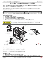
Page 125: ...art no 8434 Model Main Lift Steer Stand by 3084RT 2800 PSI 193 bar 2500 PSI 172 4 bar 2000 PSI 137 9 bar 500 550PSI 35 38 bar Adjusting Relief Valves Remove the tamper proof cap Turn adjustment screw...

Page 126: ...acorn nut Check the gauge reading again to ensure the setting did not change Turn the Standby adjustment screw counterclockwise until the gauge reads 550 PSI 38 bar Tighten the jamb nut and install t...

Page 127: ...gauge If pressure is LOW adjust steering relief valve turn clockwise and recheck If pressure is HIGH adjust steering relief valve turn counterclockwise and recheck Repeat until correct Counterbalance...

Page 128: ...to Side Forward Down Rocker Switch Potentiometer Reverse Up Rocker Switch Enable Switch Micro Switch Steer Left Matrix Module Cable Connector OFF RUN START CHOKE PREHEAT Steer Right Micro Switch GENER...

Page 129: ...er is in the tripped OFF position Common Causes of Hydraulic System Malfunctions Hydraulic fluid level is too low Incompatible hydraulic fluids mixed destroying the additives and causing varnish build...

Page 130: ...They communicate through low voltage digital signal technology called CANBUS communication The modules are protected against short circuit and reverse polarity to protect against part failure or incor...

Page 131: ...3 not used P5 1 Lift Valve P5 2 Steer Right P5 3 Steer Left P5 4 Drive Forward P5 5 Drive Reverse P5 6 Alarm P5 7 High Torque P5 8 High Speed P5 9 Hour Meter P5 10 not used P5 11 not used P5 12 not us...

Page 132: ...Switch P3 12 not used P1 1 12 Volts DC INPUT Power up P1 2 not used P1 3 CAN BUS H P1 4 Ground P1 5 not used P1 6 CAN BUS L P2 1 FORWARD DOWN P2 2 REVERSE UP P2 3 STEER Left P2 4 STEER Right P2 5 Ena...

Page 133: ...DC to the user friendly 12 volts DC used throughout the rest of the system P 600 CMEC 48V RT 21 510 601 s n 2071200014 P1 P8 P7 to Upper Controls to GP400 EZ Cal Connection P6 P5 To Pump Motor To Batt...

Page 134: ...cle P9 on the GP400 and power the system up The EZ Cal display will illuminate and read HELP PRESS ENTER From this point use the right and left arrows to scroll through the base menus Once the desired...

Page 135: ...R MACHINE MOVEMENT AT SAFE SPEEDS PERSONALITIES MUST NOT BE CHANGED WITHOUT PRIOR AUTHORIZATION FROM MEC AND MAY ONLY BE RETURNED TO FACTORY SPECIFICATION AS LISTED IN THE FOLLOWING TABLES Error Messa...

Page 136: ...P 1 5 SEC 4K 6 DELAY CLEAR 1 5 SEC 4K 7 ENTER DRIVE ELEVATED LIFT SC 40 SC X 0 DECK 4F 10 4F 11 X TILT TARGET 0 2 DEG Y TILT TARGET 0 2 DEG TILT SLACK 0 3 DEG 4G ENTER 4G 1 4G 2 4G 3 4G 4 4G 5 4G 6 UP...

Page 137: ...ER OUTPUTS 2F GP400 ANALOGS MAIN CPU 2E 1 CALDATE DATE OF CALIBRATION 2G 1 SOFTWARE SOFTWARE VERSION NUMBER 2G 2 MAX BATTERY HIGHEST BATT VOLTAGE 2G 4 BOOM GP400 ALL CIRCUITS 12V ONLY ENTER VALVE SUPP...

Page 138: ...P 1 5 SEC 4K 6 DELAY CLEAR 1 5 SEC 4K 7 ENTER DRIVE ELEVATED LIFT SC 40 SC X 0 DECK 4F 10 4F 11 X TILT TARGET 0 2 DEG Y TILT TARGET 0 2 DEG TILT SLACK 0 3 DEG 4G ENTER 4G 1 4G 2 4G 3 4G 4 4G 5 4G 6 UP...

Page 139: ...ER OUTPUTS 2F GP400 ANALOGS MAIN CPU 2E 1 CALDATE DATE OF CALIBRATION 2G 1 SOFTWARE SOFTWARE VERSION NUMBER 2G 2 MAX BATTERY HIGHEST BATT VOLTAGE 2G 4 BOOM GP400 ALL CIRCUITS 12V ONLY ENTER VALVE SUPP...

Page 140: ...amp up time to maximum 5A 6 DECEL 1 0 sec Ramp down time to stop 5A 7 MAX Height 101 Maximum drivable height 5A 8 Positrack Not Used Not Used 5A 9 Positrack Not Used Not Used 5B DRIVE PLATFORM ELEVATE...

Page 141: ...nal OFF 5H 5 Tilt 2 Second tilt setting used for increased stability Press ENTER to access 5H 5 Sub Menu 5H 5A Height 101 Point where lesser tilt angle used 5H 5B X Trip 2 1 5 sec Secondary tilt angle...

Page 142: ...of maximum height when system goes into elevated mode 6C 2 Calibrate Height Start Calibration See Section 7 for calibration of Height Sensor 6C 3 Min Lift 1 0 sec Calibration setting do not change 6C...

Page 143: ...its 2A 4 Motor Volts Real time motor voltage 2A 5 Motor 1 Real time motor amperage draw Varies depending on load and motor speed 2A 6 Temperature Motor controller chassis temp Error message too Hot at...

Page 144: ...load sense system CE only 2F OUTPUTS Numbers not listed in this table but that are displayed by EZ Cal are not used 2F 1 P4 10 Rear wheel bypass valves ON valves powered rear wheels in bypass READOUT...

Page 145: ...access to an EZ Cal some simple diagnostics are possible However it is recommended to use an EZ Cal to diagnose problems and not rely on the LED The EZ Cal provides a much higher detail of informatio...

Page 146: ...function inputs are active at the same time WAITING FOR TRIGGER A platform function is selected but the joystick trigger switch is not closed close the trigger switch to proceed TRIGGER CLOSED The joy...

Page 147: ...power ON INTERLOCKED An interlock shutdown is active preventing one or more functions The interlock can be due to many different causes Press ENTER from the MODE display to see the precise cause of t...

Page 148: ...BRATED The height and or pressure sensors have not been calibrated see CALIBRATION OF OVERLOAD SYSTEM CE option only If machine is not equipped with Overload system refer to SETUPS table and change th...

Page 149: ...ASH code is indicated The LED will flash on off a certain number of times pause off for a short delay then flash on off a second certain number of times followed by a much longer pause off The sequenc...

Page 150: ...on Messages The following are calibration HELP messages until the machine is properly calibrated for height and or pressure as required many functions will not be available NOT CALIBRATED ____________...

Page 151: ...overload features are active and the platform load is too low to be valid this could be caused by erroneous calibration a sensor fault or a change in the vehicle mechanics hydraulics FUNCTIONS LOCKED...

Page 152: ...HELP messages problems have been detected which are likely due to vehicle wiring issues FAULT ENERGIZED VALVE CHECK P5 WIRING ____________ Flash Code 3 2 FAULT VALVE FEEDBACK HIGH CHECK VALVE WIRING _...

Page 153: ...ly is out of range if the fault remains the controller may have to be replaced FAULT BAD INTERNAL SLAVE ___________________________ Flash Code 4 2 The internal slave is not operating correctly if the...

Page 154: ...points are continuously checked any significant difference generates this error This section lists CANBUS HELP messages problems have been detected with CANBUS communications between different modules...

Page 155: ...in a special factory override state In this state none of the normal shutdowns or interlocks will occur the vehicle can be freely lifted lowered and driven irrespective of any calibration needs vehic...

Page 156: ...tion no red LED at GP400 Main battery switch turned off Located left of lower control box Emergency switch pushed in or ignition switch turned off or defective Upper or lower e stop switch will cut al...

Page 157: ...in maintenance position Return maintenance lock to the stowed position Lowering valve not energized Check wiring to lowering valve located on Lift Cylinder Check for EZ Cal message or Flash code Lowe...

Page 158: ...k electrical by disconnecting valves or function by replacing valves Malfunctioning Series Parallel Valves Located on top of main hydraulic Manifold Worn hydraulic pump Check with flow meter or replac...

Page 159: ...heck steering valve for power or damage System interlock Check HELP messages using EZ Cal Hoses connected incorrectly See hydraulic section for correct connection Pressure Relief Valve RV 2 set too lo...

Page 160: ...Located inside upper control box Check switch and wiring Level Sensor not calibrated See Tilt Sensor Calibration instructions found earlier in this section System Interlock Check HELP messages using E...

Page 161: ...e to decreased weight TO REDUCE THE RISK OF ELECTRIC SHOCK ALWAYS DISCONNECT BOTH THE POWER SUPPLY CORD AND THE OUTPUT WIRES BEFORE ATTEMPTING MAINTENANCE THE CHARGER SURFACE CAN GET HOT WHILE OPERATI...

Page 162: ...atteries excessively discharged OFF OFF OFF ONE FLASH Output open circuit or short circuit or reverse polarity connection of battery to charger Battery voltage is too high may be connected to wrong vo...

Page 163: ...arity to batteries the charger is not damaged by any of these problems Red FAULT LED BLINKS twice charger has Timed Out The charger has a 22 hour timer if charge cycle is not complete within 22 hours...

Page 164: ...cap Turn adjustment screw IN to increase pressure Turn adjustment screw OUT to decrease pressure When correct pressure is obtained replace tamper proof cap with a new one Do not operate pump with tam...

Page 165: ...lve turn counterclockwise and recheck Repeat until correct Steering Relief RV2 Energize the steering to full left Hold the switch for 10 seconds to get an accurate reading on the pressure gauge If pre...

Page 166: ...ER EMERGENCY LOWERING Master Disconnect Switch PLATFORM OFF BASE LOWER Green RAISE Green EMERGENCY STOP HOUR METER Charge Indicator 15 AMP BREAKER EMERGENCY LOWERING Forward Up Rocker Switch Potentiom...

Page 167: ...YEL BLK HAND PUMP BRAKE RELEASE STEER RIGHT 107 ORG WHT HIGH SPEED 213 YEL WHT TO TANK ORLS MAIN RELIEF VALVE RIGHT FRONT A LEFT FRONT B RIGHT REAR B LEFT REAR A LEFT FRONT A ORR BRAKE PORT PULL VALV...

Page 168: ...Y BLK HIGH TORQUE 313 YEL BLK HAND PUMP BRAKE RELEASE STEER RIGHT 107 ORG WHT HIGH SPEED 213 YEL WHT TO TANK ORLS LINE SENSE RIGHT FRONT A LEFT FRONT B RIGHT REAR B LEFT REAR A LEFT FRONT A ORR GLS BR...

Page 169: ...on SV3 Spool Valve Series Parallel 4 Way 3 Position SV4 Spool Valve Series Parallel 4 Way 3 Position SVD1 Spool Valve Drive 4 Way 3 Position Callout Description STEERING COMPONENTS CYL1 Steer Cylinder...

Page 170: ...MA 3 067 LIFT CYLINDER OSCILLATING AXLE LOCK CYLINDERS TILT CYLINDER FRONT REAR 035 CL1 2500 PSI 2500 PSI 2500 PSI TILT CYLINDER SIDE SIDE 2500 PSI 2500 PSI 2000 PSI CL2 025 CL1 T B SV3 ORF4 SV6 SV7 C...

Page 171: ...P RFB LRB RRA GP PLG4 PLG4 OPL3 PLG4 OPL2 PLG4 PLG4 PLG6 CBV1 CBV2 PLG6 OPL1 PLG4 PLG4 PLG4 PLG4 PLG4 SVD1 FD1 EP1 PLG4 LS3 PD1 PD2 PD3 FD2 EP2 HP1 EC1 SV1 CL2 RV1 RV2 SV3 CL1 SP3 CL3 CV1 LS1 LS2 CV2...

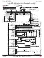
Page 172: ...Parts Manual January 2019 Section 10 Schematics 3084 All Models Hydraulic Manifold Tilt M2 ART_3111 LC1A LC2A OA LC1B LS P T2 T1 LC2B PLG4 ORF4 PLG4 ORF5 PLG8 SV9 CV3 CL1 CL1 SV8 CV4 CV5 CL1 CL1 FRON...

Page 173: ...H ROLL RIGHT ROLL LEFT AUTO LEVEL PITCH ROLL COMMON P4 1 P4 2 P4 3 P4 4 P4 5 P4 6 P4 7 P4 8 P4 9 E STOP HORN option OFF RUN START FWD DOWN JOYSTICK UPPER CONTROLS REV UP LEFT RIGHT ENABLE TILT LAMP LI...

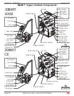
Page 174: ...h Micro Switch Steer Left Matrix Module Cable Connector OFF RUN START CHOKE GLOW Steer Right Toggle Switches Micro Switch GENERATOR Option 3084RT ANSI ART_3194 91843 91859 LIFT DRIVE HIGH SPEED MID RA...

Page 175: ...SELECTED DOWN SWITCH CHOKE PREHEAT IN START IN OIL PRESSURE SWITCH ELEVATION TRANSDUCER CE ELEVATION ANALOG IN TBM ANALOG IN GROUND GROUND GROUND P4 P5 BASE LOWER CONTROLS P6 P7 Load Sense CE P8 P8 2...

Page 176: ...108 111 110 313 213 15 408 15 15 15 15 15 15 515 43 42 414 413 412 124 120 125 415 1 2 1 2 1 2 1 2 1 2 1 2 1 2 1 2 1 2 1 2 1 2 1 2 1 2 1 2 1 2 1 2 1 1 2 3 2 PRESSURE TRANSDUCER ANGLE TRANSDUCER ANGLE...

Page 177: ...UP SWITCH PLATFORM SELECTED DOWN SWITCH CHOKE PREHEAT IN START IN OIL PRESSURE SWITCH P4 P5 BASE LOWER CONTROLS P6 P7 Load Sense CE P8 P8 2 P8 5 P8 6 P8 9 P8 13 P8 14 P8 15 ELEVATION TRANSDUCER CE ELE...

Page 178: ...107 108 111 110 313 213 15 408 15 15 15 15 15 15 515 43 42 414 413 412 124 120 125 415 PRESSURE TRANSDUCER ANGLE TRANSDUCER CE CERTIFIED ANGLE TRANSDUCER ELEVATION CAN TILT MODULE AXLE CAN BUS H CAN...

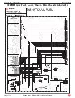
Page 179: ...START DELAY HOUR METER START 15 AMP BREAKER RAISE Green EMERGENCY STOP Master Disconnect Switch PLATFORM OFF BASE LOWER Green EMERGENCY LOWERING 3084RT Dual Fuel ANSI ART_3203 GP400 Module Diagnostic...

Page 180: ...ition SV3 Spool Valve Series Parallel 4 Way 3 Position SV4 Spool Valve Series Parallel 4 Way 3 Position SVD1 Spool Valve Drive 4 Way 3 Position Callout Description STEERING COMPONENTS CYL1 Steer Cylin...

Page 181: ...E LOCK CYLINDERS TILT CYLINDER FRONT REAR 035 1500 PSI Provision for 3 8 16 UNC Orifice Plug OPL6 CAVITY VC10 2 2500 PSI 3000 PSI 2500 PSI 2500 PSI TILT CYLINDER SIDE SIDE 2500 PSI 2500 PSI 025 T B SV...

Page 182: ...B LRB RRA GP PLG4 PLG4 PLG4 OPL3 PLG4 OPL5 PLG4 OPL4 PLG4 OPL2 PLG4 PLG4 PLG6 CBV1 CBV2 PLG6 OPL1 PLG4 PLG4 PLG4 PLG4 PLG4 PLG2 SVD1 FD1 EP1 PLG4 LS1 CP1 RV7 PD1 PD2 PD3 FD2 EP2 HP1 EC1 SV1 CL2 RV1 RV...

Page 183: ...Parts Manual January 2019 Section 10 Schematics 3084 All Models Hydraulic Manifold Tilt M2 ART_3111 LC1A LC2A OA LC1B LS P T2 T1 LC2B PLG4 ORF4 PLG4 ORF5 PLG8 SV9 CV3 CL1 CL1 SV8 CV4 CV5 CL1 CL1 FRON...

Page 184: ...SWITCH ROLL RIGHT ROLL LEFT AUTO LEVEL PITCH ROLL COMMON P4 1 P4 2 P4 3 P4 4 P4 5 P4 6 P4 7 P4 8 P4 9 E STOP HORN option OFF RUN FWD DOWN JOYSTICK UPPER CONTROLS REV UP LEFT RIGHT ENABLE TILT LAMP LI...

Page 185: ...se Up Rocker Switch Enable Switch Micro Switch Steer Left Matrix Module Cable Connector OFF RUN Steer Right Toggle Switches Micro Switch 3084ES ANSI ART_3289 91843 91859 LIFT DRIVE HIGH SPEED MID RANG...

Page 186: ...2 P7 3 P7 4 P7 7 P7 10 P7 12 P7 13 VALVE SUPPLY BASE SELECTED UP SWITCH PLATFORM SELECTED DOWN SWITCH P4 P5 BASE LOWER CONTROLS P6 P7 ANALOG INPUTS P8 P8 2 P8 5 P8 6 P8 9 P8 13 P8 14 P8 15 ELEVATION T...

Page 187: ...5 15 15 515 000 43 42 414 413 412 415 PRESSURE TRANSDUCER ANGLE TRANSDUCER CE CERTIFIED ANGLE TRANSDUCER ELEVATION 416 405 15 408 404 LEVEL MANIFOLD DOWN VALVE MAIN MANIFOLD AXLE LOCK CYLINDERS REAR W...

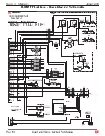
Page 188: ...TO RESET RAISE LOWER 15 AMP BREAKER EMERGENCY LOWERING CHARGE INDICATOR HOUR METER 15 AMP BREAKER RAISE Green EMERGENCY STOP Master Disconnect Switch PLATFORM OFF BASE LOWER Green EMERGENCY LOWERING 3...

Page 189: ...om Serial 12800200 3084RT From Serial 11800400 I C PU1 DRIVE PUMP Fe Fa G 3 2 15 5 1 02 MM 8 9 12 5 3 5 MM 11 2 3MM 3 2600PSI 10 4 10 3 10 2 10 1 7 GLS P AUX GP1 R R F L LR RF A B A B A B A B T LIFT C...

Page 190: ...7 10 P7 7 P7 4 P7 3 P7 2 P7 1 OIL PRESSURE SWITCH START SWITCH CHOKE PREHEAT SWITCH DOWN SWITCH PLATFORM SELECTED UP SWITCH BASE SELECTED VALVE SUPPLY GROUND GROUND TBM ANALOG IN PRESSURE SENSOR CE EL...

Page 191: ...EL BACK P3 10 P3 11 START P3 3 C D E F G H LIFT DRIVE ENABLE POTENTOMETER 3 4 GLOW PLUGS SPEED EMERG STOP TILT IND LIGHT TILT ALARM IGN START HORN 1 415 2 3 515 4 414 5 412 6 413 J8 YEL P4 6 DRIVE ENA...

Page 192: ...Page 185 Speed Level Series Service Parts Manual January 2019 Notes...

Page 193: ...d repairs and identifying and ordering the correct replacement parts All parts represented here are manufactured and supplied in accordance with MEC quality standards We recommend that you use genuine...

Page 194: ...HORN BUTTON ES Model OFF ON Switch RT Model Start Switch 515 73 422 423 421 1 3 2 429 421 AUTO LEVEL MATRIX MODULE MANUAL LEVEL SIDE TO SIDE REMOVABLE CABLE 448 449 420 SPEED TORQUE 24 420 CHOKE PREH...

Page 195: ...ly With Removable Cable ES Models 1 83065 Assembly With Removable Cable RT Models 1 6 REF Harness Removable See Wire Harness Section 6 1 7 REF Cable Removable See Wire Harness Section 6 1 All Models 8...

Page 196: ...423 422 438 MANUAL LEVEL FRONT TO REAR 415 415 E STOP HORN BUTTON 515 73 422 423 421 1 3 2 MATRIX MODULE REMOVABLE CABLE 448 449 420 SPEED TORQUE 24 420 CHOKE PREHEAT LIFT DRIVE 515 START SWITCH 3 2 1...

Page 197: ...s Section 6 1 4 16242 Weldment Control Box 1 5 13865 Bracket Control Box Holder 1 6 6350 Tape Foam 5 ft 7 50109 Screw 5 16 18 1 8 13864 Bracket Control Box Holder 1 9 50063 Washer Flat 1 10 8826 Thumb...

Page 198: ...ervice Parts Manual January 2019 Section 11 Controls Upper Control Box Cover Assembly Early Style ART_2220 R3 Control Box Cover Assembly 2 1 3 4 5 6 29 28 7 8 9 11 13 15 19 20 24 25 32 26 27 16 17 18...

Page 199: ...Large 1 12 HDW8531 Washer Flat 2 13 HDW7881 Washer Bevel 1 14 3782 Cam Directional 1 15 13403 Plate Bottom 1 16 6917 Clamp Cable 1 4 Inch 1 17 7818 Bearing Bronze Flanged 1 18 HDW3771 Washer Flat 1 1...

Page 200: ...rvice Parts Manual January 2019 Section 11 Controls Upper Control Joystick Early Style ART_2221 R1 Control Arm Joystick Reference ART_188 3 4 9 10 2 1 6 12 13 14 11 11 8 5 7 Connect Purple and Blue wi...

Page 201: ...8455 Screw Service Only 4 4 8752 Grip Top Half Service Only 1 5 8751 Grip Bottom Half Service Only 1 6 13638 Control Arm Without Wire 1 7 8748 Trigger Service Only 1 8 8456 Rocker Boot Service Only 1...

Page 202: ...eed Level Series Service Parts Manual January 2019 Section 11 Controls Upper Control Box Assembly Early Style Upper Control Box Assembly J R Merrit Speed Level Series Art_5392 ILLUSTRATION No 7 1 4 5...

Page 203: ...1 7875 Gasket 1 2 18660 Joystick Box Weldment 1 3 28542 Palm Rest Weldment 1 4 50191 THMS 10 32X00 50 ZP 4 5 50238 NNYL 10 32 05 Z 4 6 50330 THMS 10 32X01 00 ZP 4 7 90729 Decal Upper Control Joystick...

Page 204: ...r Circuit Breaker Emergency Lower Toggle Switch Emergency Lower Toggle Switch Emergency Stop Circuit Breaker TBM Alarm Platform Base Selector Switch Platform Base N O GP400 Connector Lower Green Raise...

Page 205: ...1 7 7423 Switch Toggle 1 Pole 2 Position 3 1 8 9 8082 Contact Block N O 4 10 91711 Alarm 107dB 1 11 17082 Bracket Alarm Mount 1 12 91838 Terminal Block Module TBM 1 13 91659 System Controller GP400 1...

Page 206: ...Toggle Switch Emergency Stop complete switch Circuit Breaker TBM Alarm Platform Base Selector Switch Platform Base N O GP400 Connector Start N O Choke N O Lower Green Raise Green Start Green 30 Sec D...

Page 207: ...it Breaker 1 9 7423 Switch Toggle 1 Pole 2 Position 3 1 10 8083 Contact Block N C 1 11 8082 Contact Block N O 7 12 91711 Alarm 107dB 1 13 17082 Bracket Alarm Mount 1 14 91838 Terminal Block Module TBM...

Page 208: ...tch Emergency Lower Toggle Switch Emergency Stop complete switch Circuit Breaker TBM Alarm Platform Base Selector Switch Platform Base N O GP400 Connector Start N O Preheat N O Lower Green Raise Green...

Page 209: ...cuit Breaker 1 9 7423 Switch Toggle 1 Pole 2 Position 3 1 11 8082 Contact Block N O 6 12 91711 Alarm 107dB 1 13 17082 Bracket Alarm Mount 1 14 91838 Terminal Block Module TBM 1 15 91659 System Control...

Page 210: ...Installation To Serial 11800046 ART_3114 Platfrom Installation Speed Level Sigma Lift 5 3 4 7 5 6 6 5 4 7 5 5 3 6 4 2 1 Top Bolted Ladder Side Bolted Ladder Typical Installation 3084 Platform Shown P...

Page 211: ...er Description Qty 1 83083 Boom Assembly REF 2 83080 83160 Platform Assembly 3084 REF 83097 Platform Assembly 2684 REF 3 19258 Ladder Side Bolted 1 19148 Ladder Top Bolted 1 4 50040 Bolt M12 x 35 GR8...

Page 212: ...latform Rails 3084 To Serial 11800046 ART_3113 3084 Platform Rails Speed Level Sigma Lift 5 5 5 7 16 17 18 18 18 15 4 13 24 12 22 23 29 30 31 29 30 31 24 22 23 24 22 23 x2 24 22 23 24 11 8 14 20 2 3 1...

Page 213: ...Hinge Up To Serial 11800033 2 91888 Hinge Serial 11800034 Up 2 14 50125 Bolt 6mm x 55 8 15 50047 Nut 6mm 10 16 8909 Manual Enclosure 1 17 50028 Bolt 6mm x 20 8 18 50000 6mm Washer 10 19 19228 Front G...

Page 214: ...l 11800047 3084 Platform 3084 Speed Level Series Art_5374 ILLUSTRATION No 14 19 13 18 5 22 2 3 7 24 21 12 11 15 8 17 20 9 6 16 10 1 23 OPTIONAL 6X BRACKET ATTACH 3923 12X NNYL M10 X 1 50 0B ZP NYLON I...

Page 215: ...Gate Hinge 2 11 84148 Reinforcement Rail Corner Assy 2 12 83165 Front Right Rail Assy 1 19141 Front Right Rail Only 1 13 83164 Front Left Rail Assy 1 19136 Front Left Rail Only 1 14 83161 Platform Si...

Page 216: ...uary 2019 Section 12 Platform and Rails Platform Rails 2684 Part 1 ART_3476 2684 Platform Rails 1 of 2 Speed Level Sigma Lift Guard Rail Detail x16 3 4 5 23 13 14 12 12 1 22 24 25 2 2 23 2 2 18 x2 20...

Page 217: ...olt 6mm x 55 8 8 50000 Washer M6 Flat 8 9 50047 Nut M6 Nylock 8 10 19239 Backing Plate Hinge 4 11 50039 Screw M12x1 75 x 30 10 12 91593 Bearing 10 13 19399 Roller 2 14 19398 Axle Threaded 2 15 19131 R...

Page 218: ...77 2684 Platform Rails 2 of 2 Speed Level Sigma Lift Guard Rail Detail x16 30 12 54 27 32 33 34 55 26 52 14 13 12 29 31 28 41 36 36 37 not shown x2 38 39 39 40 not shown x4 36 37 x3 35 36 x3 36 37 x2...

Page 219: ...28 19432 Side Rail Deck Extension Left Side 1 29 92219 Spring Pin M8 x 55 1 30 19367 Deck Extension Handle Weldment 1 31 19370 Deck Extension Bar 1 32 19374 Gate Material Loading 1 33 8909 Manuals Ca...

Page 220: ...vice Parts Manual January 2019 Boom Mount and Pivot ART_3115 Boom Mount and Pivot Speed Level Sigma Lift 2 16 17 5 11 7 8 14 15 9 8 14 15 9 10 10 10 4 13 13 12 3 1 6 CYLINDER MOUNT DETAIL 18 19 Boom M...

Page 221: ...Retainer 1 7 50023 Bolt M12 x 50 6 8 19122 Pin 4 9 50119 Nut Nylock 1 1 4 8 10 19081 Cylinder Level 2 11 50039 Bolt M12 x 30 1 12 92011 Bearing Flange 4 13 50007 Washer M12 Nord Lock 6 14 50065 Flat...

Page 222: ...2684ES From Serial 12700041 3084RT From Serial 11800400 3084ES From Serial 11700089 Chassis Planetary Drive Assembly Speed Level Series Art_5386 ILLUSTRATION No 22 20 28 14 17 33 24 47 32 15 2 4 27 31...

Page 223: ...0 ZP Standard Flat 4 26 50006 WSHR M10 ZP Nordlock 40 27 50007 WSHR M12 ZP Nordlock 1 28 50028 HHCS M06 1 00X020 08 ZP F 4 29 50033 HHCS M10 1 50X025 08 ZP F 4 30 50034 HHCS M10 1 50X030 08 ZP F 8 31...

Page 224: ...217 Speed Level Series Service Parts Manual January 2019 Section 13 Boom Side Port Assembly Side Port Assembly Speed Level Series Art_5385 ILLUSTRATION No 1 2 3 FRONT LEFT FRONT RIGHT REAR LEFT REAR R...

Page 225: ...peed Level Series Service Parts Manual January 2019 Section 13 Boom Item Part Number Description Qty 1 93710 Omni Gear VB04 WHL DRV Planetary 1 2 93965 129CC HYD Motor Side Ports 1 3 94756 O Ring AS 5...

Page 226: ...on 13 Boom Lower Boom Assembly ART_3116 Lower Linkage Installation Speed Level Sigma Lift ANSI Qty 1 CE Qty 2 7 6 14 4 14 18 27 26 28 21 15 16 15 16 16 14 32 33 14 14 3 13 15 12 1 22 24 23 25 30 31 2...

Page 227: ...sducer Model 120 1 CE Specifications EZfit Angle Transducer Model 120 2 13 50016 ANSI Specifications Screw M8 x 55 2 CE Specifications Screw M8 x 55 4 14 92011 Flange Bearing 8 15 50001 M8 Washer 10 1...

Page 228: ...eries Service Parts Manual January 2019 Section 13 Boom Upper Boom Assembly ART_3117 Boom Assembly Speed Level Sigma Lift 1 8 3 17 18 19 18 19 10 16 22 18 26 7 11 21 12 11 21 12 6 14 13 4 8 23 25 24 8...

Page 229: ...20 1 5 REF Lower Tension Weldment See Lower Boom Assembly On Page 220 1 6 19199 Gear Pivot 1 7 19055 Boom Pivot Weldment 1 8 92011 Flange Bearing 8 9 10 19121 Boom Mount Pin 6 11 18152 Pin Retainer 6...

Page 230: ...ont Axle Assembly ART_3118 Front Axle Assembly Speed Level Sigma Lift Hydraulic Wheel Motor A B 5 6 3 22 4 2 7 9 17 18 28 29 12 9 8 13 8 14 11 10 16 18 17 1 19 20 25 19 15 21 24 27 Drive Ports 22 26 C...

Page 231: ...Motor LH Front 1 12 50012 Screw M16 X 50 GR 12 Socket Head 16 13 50008 Lock Washer M16 16 14 50072 Screw 13 2 50 LG GR 8 Socket Head 8 15 HDW8457 Nut 13 GR8 8 16 10709 Hub 2 17 HDW8568 Nut 1 1 8 18 6...

Page 232: ...ed Level Series Service Parts Manual January 2019 Section 14 Axles Axle Installation Front ART_3119 Front Axle Installation Speed Level Sigma Lift 10 5 17 18 16 14 9 12 15 13 9 14 16 4 10 6 16 14 14 7...

Page 233: ...ire Assy RH 10 PLY Foam ANSI Option CE Standard 1 91577 Wheel Tire Assy RH Non Marking Pneumatic ANSI Option 1 91579 Wheel Tire Assy RH Non Marking Foam ANSI CE Option 1 91581 Wheel Tire Assy RH Turf...

Page 234: ...nuary 2019 Section 14 Axles Axle Installation Rear ART_3120 Rear Axle Installation Speed Level Sigma Lift Rear Hydraulic Wheel Motor with Brake A B 20 7 9 16 16 2 13 1 3 14 5 5 10 6 11 15 4 4 21 20 8...

Page 235: ...Tire Assy RH Turf Pneumatic ANSI Option 1 Incl 91180 Wheel Service 3 50165 Nut Lug 20 GR 5 12 4 16349 Bottom Hose Cover 2 5 19168 Top Hose Cover 2 6 50010 Screw M8 x 25 2 7 50001 Washer Lock M8 2 8 50...

Page 236: ...Shaft Bearing 1d 1c 1b Front Housing 1a DT710 BRAKE MOTOR COMPONENTS Shaft Key 1f 1h Piston Capscrews 8 Shaft Nut Spacer Shims 1 3 Shaft Bearing Shaft Bearing 1c 1j Piston Spring Assembly Bolts 7 1m 1...

Page 237: ...1 1e Incl Small Piston O Ring Seal 1 1f Incl Small Piston Seal 1 1g Incl Large Piston O Ring Seal 1 1h Incl Large Piston Seal 1 1i Incl O Ring Seal 1 1j Incl Body Seal 3 1k Incl Manifold Seal 1 1l In...

Page 238: ...s 7 I D Tag Assembly Endcover Piston Spring Rotor Assembly Divider Plate Endcover Piston Commutator Assembly Drive Link Manifold Rear Housing Bearing Shaft Housing Shaft Key Thrust Washers 2 Thrust Be...

Page 239: ...Hyd Painted 1 90592 Seal Kit 1a Incl Dust Seal 1 1b Incl High Pressure Seal 1 1c Incl Metal Backup Shim 1 1d Incl Teflon Back Up Seal 1 1e Incl Shaft Seal 1 1f Incl Housing Seal 1 1g Incl Body Seals 3...

Page 240: ...ly Electric Models Part 1 ART_3170 ES Manifold Assembly Sheet 1 of 2 ES MODELS FRONT LEFT BACK RIGHT 9 13 12 20 26 6X 8 1 16 10 21 23 26 23 26 24 26 24 26 2 19 3 14 4 17 17 25 26 26 26 25 26 15 15 7 1...

Page 241: ...476 Valve Relief 1 8 91151 Valve Piloted Spool 4 Way 3 Position 3 9 91152 Valve Piloted Poppet 2 10 91012 Valve Manual Pull 1 11 91153 Valve Load Shuttle Check 1 12 91350 Valve Counterbalance 2 13 911...

Page 242: ...vice Parts Manual January 2019 Section 15 Hydraulics Main Manifold Assembly Electric Models Part 2 ART_3171 ES Manifold Assembly Sheet 2 of 2 ES MODELS FRONT LEFT BACK RIGHT 31 31 41 41 42 35 36 41 39...

Page 243: ...le O Ring Male MB MJ90LL 4 4 1 35 50647 Elbow 90 Male O Ring Male MB MJ90L 4 4 1 36 50763 Fitting Male O Ring Male MB MJ 12 12 1 37 50659 Fitting Male O Ring Male MB MJ 12 8 1 38 50799 Fitting Male 37...

Page 244: ...ary 2019 Section 15 Hydraulics Main Manifold Assembly RT Models Part 1 ART_3172 RT Manifold Assembly Sheet 1 of 2 RT MODELS FRONT LEFT BACK RIGHT 9 15 13 26 6X 8 1 17 10 22 24 26 24 26 3 20 2 14 4 18...

Page 245: ...50 Valve Relief Steer 1 8 91151 Valve Piloted Spool 4 Way 3 Position 3 9 91152 Valve Piloted Poppet 2 10 91012 Valve Manual Pull 1 11 91153 Valve Load Shuttle Check 1 12 91154 Valve Load Shuttle Check...

Page 246: ...es Service Parts Manual January 2019 Section 15 Hydraulics Main Manifold Assembly RT Models Part 2 ART_3173 RT Manifold Assembly Sheet 2 of 2 RT MODELS FRONT LEFT BACK RIGHT 31 31 44 44 41 42 35 36 41...

Page 247: ...4 4 1 35 50647 Elbow 90 Male O Ring Male MB MJ90L 4 4 1 36 50763 Elbow 90 Male O Ring Male MB MJ 12 12 1 37 50821 Elbow 90 Male O Ring Male MB MJ90LL 12 12 1 38 50658 Fitting Male 37 JIC Male 37 O Rin...

Page 248: ...e 241 Speed Level Series Service Parts Manual January 2019 Section 15 Hydraulics Leveling Manifold Assembly ART_3205 Leveling Manifold Speed Level Sigma Lift FRONT BOTTOM LEFT RIGHT 8 9 10 4 1 2 3 6 7...

Page 249: ...ption Qty 83093 Leveling Manifold Assembly W Fittings 1 1 19300 Leveling Manifold Assembly W o Fittings 1 2 92123 Valve 2 3 91143 Coil 2 4 91473 Check Valve 1 5 6 50661 Fitting MB MJ 90LL 6 4 MB MJ 90...

Page 250: ...l January 2019 Section 15 Hydraulics RT Manifold Assembly 2684RT From Serial 12800107 2684ES From Serial 12700041 3084RT From Serial 11800400 3084ES From Serial 11700089 RT Manifold Assembly Speed Lev...

Page 251: ...K08J 01 C N 0 HYDAC 2610215 1 2 94082 Coil 12DN 32 1329 HYDAC 2610149 1 3 94083 Coil 12DN 40 1836 HYDAC 3012600 2 4 94087 Valve 3W2P SO WK06C 01 C N 0 HYDAC 2610183 1 5 94452 XX92 Main Manifold Alt Fo...

Page 252: ...4ES From Serial 12700041 3084RT From Serial 11800400 3084ES From Serial 11700089 ART_3199 Hydraulic Hose Routing Steer Brake Case Drain Speed Level Sigma Lift RT MODELS STR STL B FRONT RIGHT LEFT BOTT...

Page 253: ...y 1 4 x 86 4G4FJX 4G4FJX90S 1 4 19361 Hose Assy 1 4 x 73 4G4FJX 4G4FJX90S 1 5 19362 Hose Assy 1 4 x 52 4G4FJX 4G4FJX90S 1 6 19363 Hose Assy 1 4 x 89 4G4FJX 4G4FJX 2 7 19364 Hose Assy 1 4 x 77 4G4FJX 4...

Page 254: ...raulic Hose Routing Lift and Pump Speed Level Sigma Lift LS LFT ORLS ORS P P T2 T1 T FRONT RIGHT LEFT BOTTOM LC1A LC2A OA LC1B LS P T2 T1 LC2B FRONT BACK RIGHT LEFT GSTR ORS LFT P RFB LRB RRA GP STR B...

Page 255: ...1 5 19370 Hose Assy 1 4 x 33 4G4FJX 4G4FJX90S 1 6 19343 Hose Assy 3 4 x 90 12G12FJX 12G12FJX90S 1 7 19347 Hose Assy 3 4 x 21 12G12FJX 12G12FJX90S 1 8 91423 Hose Assy 3 4 X 82 12M3K 12FJX 12FJX45 1 9...

Page 256: ...tform Level Axle Float ART_3201 Hydraulic Hose Routing Level and Axle Float Speed Level Sigma Lift LC1A LC2A LC1B LC2B LC1A LC2A LC1B LC2B OA FRONT RIGHT LEFT BOTTOM LC1A LC2A OA LC1B LS P T2 T1 LC2B...

Page 257: ...2019 Section 15 Hydraulics Item Part Number Description Qty 1 19349 Hose Assy 1 4 x 120 4G4FJX 4G4FJX 4 2 90316 Hose Assy 1 4 x 21 4G4FJX 4G4FJX 1 3 19361 Hose Assy 1 4 x 73 4G4FJX 4G4FJX90S 1 4 1934...

Page 258: ...odels Drive Motors ART_3202 Hydraulic Hose Routing Drive Motors Speed Level Sigma Lift U A U B L B L A U A U B L B L A FRONT RIGHT LEFT BOTTOM LC1A LC2A OA LC1B LS P T2 T1 LC2B FRONT BACK RIGHT LEFT G...

Page 259: ...Assy 1 2 x 49 8M3K 8FJX 8FJX45 2 2 3 19357 Hose Assy 1 2 x 10² 8M3K 8FJX 8FJX45 2 4 5 19353 Hose Assy 1 2 x 61 8M3K 8FJX 8FJX 2 6 19352 Hose Assy 1 2 x 37 8M3K 8FJX 8FJX90S 2 7 8 19354 Hose Assy 1 2...

Page 260: ...Brake Case Drain ART_3208 Hydraulic Hose Routing Steer Brake Case Drain Speed Level Sigma Lift STR STL B FRONT RIGHT LEFT BOTTOM LC1A LC2A OA LC1B LS P T2 T1 LC2B GSTR ORS LFT P RFB LRB RRA GP STR B...

Page 261: ...se Assy 1 4 x 15 4G4FJX 4G4FJX90S 1 3 19359 Hose Assy 1 4 x 86 4G4FJX 4G4FJX90S 2 4 19361 Hose Assy 1 4 x 73 4G4FJX 4G4FJX90S 1 5 19362 Hose Assy 1 4 x 52 4G4FJX 4G4FJX90S 1 6 19363 Hose Assy 1 4 x 89...

Page 262: ...raulic Hose Routing Lift and Pump Speed Level Sigma Lift LS LFT ORLS ORS P P T2 T1 T FRONT RIGHT LEFT BOTTOM LC1A LC2A OA LC1B LS P T2 T1 LC2B FRONT BACK RIGHT LEFT GSTR ORS LFT P RFB LRB RRA GP STR B...

Page 263: ...X 1 3 91909 Hose Assy 3 8 x 150 6G6FJX 6G6FJX 1 4 91879 Hose Assy 3 4 x 16 12G12FJX 12G12FJX 1 5 19347 Hose Assy 3 4 x 21 12G12FJX 12G12FJX90S 1 6 90315 Hose Assy 1 2 x 21 8G8FJX 8G8FJX90S 1 7 19369 H...

Page 264: ...orm Level Axle Float ART_3210 Hydraulic Hose Routing Level and Axle Float Speed Level Sigma Lift LC1A LC2A LC1B LC2B LC1A LC2A LC1B LC2B OA FRONT RIGHT LEFT BOTTOM LC1A LC2A OA LC1B LS P T2 T1 LC2B GS...

Page 265: ...2019 Section 15 Hydraulics Item Part Number Description Qty 1 19349 Hose Assy 1 4 x 120 4G4FJX 4G4FJX 4 2 90316 Hose Assy 1 4 x 21 4G4FJX 4G4FJX 1 3 19361 Hose Assy 1 4 x 73 4G4FJX 4G4FJX90S 1 4 1934...

Page 266: ...els Drive Motors ART_3211 Hydraulic Hose Routing Drive Motors Speed Level Sigma Lift U A U B L B L A U A U B L B L A FRONT RIGHT LEFT BOTTOM LC1A LC2A OA LC1B LS P T2 T1 LC2B GSTR ORS LFT P RFB LRB RR...

Page 267: ...Assy 1 2 x 49 8M3K 8FJX 8FJX45 2 2 3 19357 Hose Assy 1 2 x 10² 8M3K 8FJX 8FJX45 2 4 5 19353 Hose Assy 1 2 x 61 8M3K 8FJX 8FJX 2 6 19352 Hose Assy 1 2 x 37 8M3K 8FJX 8FJX90S 2 7 8 19354 Hose Assy 1 2...

Page 268: ...Page 261 Speed Level Series Service Parts Manual January 2019 Section 15 Hydraulics Lift Cylinder ART_3206 Lift Cylinder Sigma Level 1 3 3 4 5 6 7 2 8...

Page 269: ...Hydraulics Item Part Number Description Qty 1 19084 Lift Cylinder 1 92077 Seal Kit 2 6669 Bearing 4 3 50776 Fitting MB MJ 6 6 2 4 50890 Fitting MJ FJX 90 6 6 1 5 91732 Orifice 1 6 91464 Valve 2 Way NC...

Page 270: ...ies Service Parts Manual January 2019 Section 15 Hydraulics Steering Cylinder ART_2713 X72 Steering Cylinder 91019 Steering Cylinder PISTON PISTON SEAL WEAR RING STATIC SEAL ROD SEAL ROD WIPER SEAL KI...

Page 271: ...ry 2019 Section 15 Hydraulics Item Part Number Description Qty 91019 Steering Cylinder 2 90990 Seal Kit Service 1 50769 Adapter Male O Ring Male JIC 1 2 50962 Tee MJ MB MJT 4 1 3 HDW5925 Jamnut 5 8 18...

Page 272: ...Page 265 Speed Level Series Service Parts Manual January 2019 Section 15 Hydraulics Level Cylinder ART_3219 Level Cylinder Sigma Level 1 3 2...

Page 273: ...d Level Series Service Parts Manual January 2019 Section 15 Hydraulics Item Part Number Description Qty 1 19081 Level Cylinder 2 92078 Seal Kit Service 2 92125 Counterbalance Valve 4 3 50665 Fitting M...

Page 274: ...Page 267 Speed Level Series Service Parts Manual January 2019 Section 15 Hydraulics Axle Lock Cylinder ART_3220 Axle Lock Cylinder Sigma Level 1 3 2 2 4...

Page 275: ...evel Series Service Parts Manual January 2019 Section 15 Hydraulics Item Part Number Description Qty 1 19087 Axle Lock Cylinder 2 92079 Seal Kit Service 2 7896 Bearing 4 3 92192 Valve 1 4 50665 Fittin...

Page 276: ...Level Series Service Parts Manual January 2019 Module Installation ART_3121 Module Installation Speed Level Sigma Lift 2 1 16 17 4 3 8 6 7 12 13 14 12 5 9 10 19 20 21 10 18 11 11 Module Installation S...

Page 277: ...6 19106 Module Bracket Right Front 1 7 19105 Module Bracket Right Rear 1 8 19104 Module Bracket Left Rear 1 9 19103 Module Bracket Left Front 1 10 50039 Bolt M12 x 30 24 11 50003 Washer M12 24 12 5005...

Page 278: ...S To Serial 12700029 3084ES To Serial 11700042 ART_3122 Control Module Drawing 1 of 2 Speed Level Sigma Lift ES MODELS 22 3 2 20 24 15 18 19 17 5 9 27 19 25 26 5 20 21 x2 not shown 22 7 _ 8 6 23 4 10...

Page 279: ...58 Motor Controller 1 10 19276 Heat Sink 1 11 93173 Fuse 1 93174 Base 1 12 91745 Contactor Solenoid 48V 12V Coil 1 13 8368 Diode 1 14 9370 Fluid Level Gauge 1 15 6121 Trim Lock 5 ft 16 91633 Battery C...

Page 280: ...l 12700029 3084ES To Serial 11700042 ART_3123 Control Module Drawing 2 of 2 Speed Level Sigma Lift ES MODELS PU SH FO R EM ER GE NC Y ST OP EM ER GE NC Y LO WE RIN G TW IST TO RE SE T RA ISE LO WE R P...

Page 281: ...IC 1 9 6156 Filter Cartridge 1 10 50650 Nipple MJ MP 12 20 1 11 9367 Filler Strainer 1 12 50143 Bolt 32 1 57 6 13 14 50031 Screw Hex M8 x 25 4 15 50048 Nut M8 Nylock 4 16 5000 Washer M8 4 17 50147 Scr...

Page 282: ...uary 2019 Section 16 Base Power Module ES 2684ES To Serial 12700029 3084ES To Serial 11700042 ART_2719 Power Module 3072ES 3772ES Sigma Level ES 14 18 4 3 16 17 9 7 8 10 20 19 5 13 24 12 1 18 11 18 17...

Page 283: ...attery Holddown 1 8 2987 Holddown Rod 2 9 6110 Wingnut 2 10 91641 Battery 375 AH UL16 8 11 16619 Bracket Battery 1 12 16620 Shelf Battery 5 13 90898 Battery 12VDC 17 18 AH 1 14 HDW5724 Screw 5 16 18 L...

Page 284: ...2019 Section 16 Base Control Module RT Drawing 1 of 2 2684RT To Serial 12800038 3084RT To Serial 11800078 ART_3077 Control Module Drawing 1 of 2 Speed Level Sigma Lift 15 22 21 3 2 16 23 20 8 27 26 19...

Page 285: ...Battery Disconnect 1 9 10 11 12 13 14 15 16152 Bulkhead 1 16 83071 Hydraulic Manifold See Section 5 Hydraulics 1 17 83093 Manifold Leveling See Section 5 Hydraulics 1 18 50237 Screw Hex M8 x 100 3 19...

Page 286: ...19 Section 16 Base Control Module RT Drawing 2 of 2 2684RT To Serial 12800038 3084RT To Serial 11800078 ART_3078 Control Module Drawing 2 of 2 Speed Level Sigma Lift 1 18 17 10 12 9 11 13 14 6 13 2 3...

Page 287: ...Male 1 8 NPT 5 16 Hose Barb 1 7788 Clamp Not Shown 1 6458 Hose Fuel Line Not Shown 90 in 6 16225 Bracket Fuel Tank 1 7 83078 Dual Duel Models Control Box Assy 1 83079 Diesel Models Control Box Assy 1...

Page 288: ...ly 2684ES From Serial 12700030 3084ES From Serial 11700043 ES Control Module Assembly Speed Level Series Art_5387 ILLUSTRATION No 11 3 29 27 17 17 13 40 7 18 13 24 21 39 24 18 13 14 13 34 32 18 5 38 2...

Page 289: ...048 NNYL M08X1 25 08 ZP Nylon Inse 29 19 50049 NNYL M10X1 50 08 ZP Nylon Inse 4 20 50214 HHCS M06 1 00X030 08 ZP P 6 21 50219 HHCS 03 08 16X00 75 05 ZP 4 22 50237 HHCS M08 1 25X100 08 ZP P 3 23 50295...

Page 290: ...Section 16 Base RT Control Module Assembly 2684RT From Serial 12800039 3084RT From Serial 11800079 RT Control Module Assembly Speed Level Series Art_5388 ILLUSTRATION No 11 21 31 15 12 16 20 14 19 30...

Page 291: ...91179 Control Box 1 16 91157 Control Box Cover 1 17 9370 Gauge Level Hyd Tank 1 18 8841 Switch Battery 1 19 92565 Internal Filter 1 20 92563 Tank Filler W Strainer 1 21 50030 HHCS M8 1 25 X 20 GR 8 8...

Page 292: ...s Service Parts Manual January 2019 Section 16 Base Power Module RT 2684RT To Serial 12800038 3084RT To Serial 11800078 ART_3478 Power Module 91RT Speed Level RT 1 2 8 9 10 7 3 18 4 6 5 11 14 12 19 16...

Page 293: ...M6 x 20 11 8 50068 Washer M6 Fender 13 9 50047 Nut M6 Nylock 12 10 HDW5724 Screw 5 16 18 x 3 4 Inch GR5 4 11 9370 Level Gauge 1 12 HDW9200 Plug 1 4 NPT 1 13 6156 Filter Cartridge 1 14 50664 Elbow MP M...

Page 294: ...Base ES Power Module Assembly 2684ES From Serial 12700030 3084ES From Serial 11700043 ES Power Module Assembly Speed Level Series Art_5389 ILLUSTRATION No 1 4 20 16 27 19 18 10 17 25 25 12 9 8 19 18...

Page 295: ...19437 Fuel Fill Cover 1 12 19446 Battery Cross Brace 1 13 19288 Battery Stop 2 14 19445 Battery Bracket 1 15 92634 Spring Nut M8 1 25X20 25 6 16 50002 WSHR M10 ZP Standard Flat 4 17 50295 HHCS M08 1...

Page 296: ...Section 16 Base Diesel Power Module Assembly Diesel Power Module Assembly Speed Level Series Art_5390 ILLUSTRATION No 10 17 18 8 9 18 17 2 26 6 27 6 28 28 19 29 15 12 3 16 5 13 21 24 23 11 16 18 30 3...

Page 297: ...adiator 2 14 92978 Spring Num M8 1 25X20 25 6 15 16210 Spacer Engine 3 16 50030 HHCS M8 1 25 X 20 GR 8 8 ZP 13 17 50001 WSHR M08 ZP Standard Flat 9 18 50048 NNYL M08X1 25 08 ZP Nylon Inse 11 19 50116...

Page 298: ...2019 Section 16 Base Dual Fuel Power Module Assembly Dual Fuel Power Module Assembly Speed Level Series Art_5391 ILLUSTRATION No 19 20 8 9 28 28 21 4 1 22 19 20 2 23 6 20 19 7 18 17 3 5 16 15 12 29 1...

Page 299: ...4 91131 Radiator Bracket Kit 1 15 91127 Coolant Overflow Tank 1 16 92634 Spring Nut M8 1 25X20 25 6 17 50000 WSHR M06 ZP Standard Flat 2 18 50296 HHCS M06 1 00X15 08 ZP P 2 19 50001 WSHR M08 ZP Standa...

Page 300: ...293 Speed Level Series Service Parts Manual January 2019 Section 16 Base Engine Mount Dual Fuel ART_2126 R1 Engine Mount DF752 Dual Fuel 3 12 19 14 15 2 4 17 13 12 16 1 10 18 11 6 7 8 5 9 DUAL FUEL MO...

Page 301: ...oolant Overflow Tank 1 6 50028 Screw M6 x 20 2 7 50047 Nut M6 Nylock 2 8 6458 Hose 3 ft 9 16295 Air Intake Weldment 1 10 HDW5723 Air Intake Weldment 2 11 HDW8267 Nut 1 4 20 4 12 7736 Insulator Rubber...

Page 302: ...ed Level Series Service Parts Manual January 2019 Section 16 Base Engine Mount Diesel ART_2127 R2 Engine Mount D1105 Diesel 3 10 21 14 15 2 17 13 12 16 23 24 25 18 19 20 23 8 9 7 8 22 11 4 1 5 21 12 D...

Page 303: ...w M6 x 20 2 9 50047 Nut M6 Nylock 2 10 6458 Hose 3 ft 11 16295 Air Intake Weldment 1 12 7736 Insulator Rubber 8 13 40620 Spacer Isolator 4 14 HDW8567 Washer Flat 3 8 4 15 HDW8279 Screw 3 8 16 x 2 1 2...

Page 304: ...2019 Section 16 Base Engine Diesel ART_2130 R4 Diesel Engine Kubota D1105 28 27 27 13 20 21 14 15 37 36 39 40 41 42 Throttle Relay Glow Plug Relay 35 38 43 44 33 10 11 12 19 18 3 6 1 16 17 25 26 23 2...

Page 305: ...4 Valve Check 1 17 7788 Hose Clamp 5 18 8413 Starter Incl 19 90227 Alternator Incl 20 91124 Fuel Solenoid Incl 21 9832 Glow Plugs Incl 22 91112 KTR Housing Kit D905 1 22a 91572 Coupler Outer 23 91130...

Page 306: ...anuary 2019 Section 16 Base Engine Dual Fuel ART_2129 R4 Dual Fuel Engine Kubota DF752 42 43 44 45 41 46 50 17 3 4 7 2 6 5 28 52 47 48 49 51 19 20 26 25 21 23 24 Coil 27 16 15 13 8 9 14 18 1 30 31 29...

Page 307: ...Shutoff 1 10 92533 Clamp 1 1 2 1 54 92945 Solenoid Propane Shutoff 1 11 55 92944 Wire Assembly Gas Shutoff Solenoid 1 12 56 91046 Manifold Exhaust 1 13 93632 Air Cleaner Assembly 1 57 91559 Gasket Mu...

Page 308: ...Page 301 Speed Level Series Service Parts Manual January 2019 Section 16 Base LP Tank Dual Fuel ART_2128 R2 LP Tank Dual Fuel 1 2 5 3 10 7 9 4 6 11 5 12 8 Control Module 13 DUAL FUEL MODELS...

Page 309: ...Quick Disconnect 1 3 6890 Hose Assembly 30 1 4 7406 Hose Assembly 90 1 5 HDW6894 Elbow Brass NPT to SAE 45 2 6 6861 Bulkhead Filter 1 7 6860 Bracket Tank Mount 1 8 19102 Tank Support Weldment 1 9 5003...

Page 310: ...peed Level Series Service Parts Manual January 2019 Section 16 Base Generator Option RT Old Style ART_2135R1 Generator Option RT MODELS ROTATE 90 Control Module Upper Controls 1 16 10 12 11 13 14 9 8...

Page 311: ...Item 1 4 91002 Coil 12V 10 Series Included With Item 1 5 91546 Needle Valve Included With Item 1 6 7 91544 Plug Male 3 Prong 1 8 91545 Receptacle Female 2 9 7594 Strain Relief 1 10 11 7617 Wire 14GA 3...

Page 312: ...ES MODELS Control Module not to scale Axle Tilt Sensor B M Fuse Main Disconnect Solenoid Axle Lock Cylinder Lift Cylinder Wheel Motor Axle Lock Cylinder Motor Control Aux Manifold Main Manifold Motor...

Page 313: ...om To Upper Control Box Removable Control Box 1 92195 Harness Communication Platform Bottom To Upper Control Box Fixed Control Box 1 11 9441 Cable Power to Platform 3084 Not Shown Connects Plug On Mod...

Page 314: ...ed Level Sigma Lift RT Models UPPER CONTROLS RT MODELS Control Module not to scale To 5 Axle Tilt Sensor Main Disconnect Axle Lock Cylinder Lift Cylinder Wheel Motor Axle Lock Cylinder Aux Manifold To...

Page 315: ...n Boom Pivot Angle CAN Tilt Adapter 1 9 92141 Harness Communication Boom Pivot Angle CAN Tilt To Platform Bottom 1 10 91780 Harness Communication Platform Bottom To Upper Control Box Removable Control...

Page 316: ...ORM WHILE IN MOTION 13 DO NOT RECHARGE BATTERIES NEAR SPARKS OR OPEN FLAME BATTERIES EMIT HIGHLY EXPLOSIVE HYDROGEN GAS 14 DO NOT PERFORM SERVICE ON THE MACHINE WITHOUT PROPERLY SUPPORTING ELEVATING A...

Page 317: ...45 Decal Danger Electric Tipover Wind Rating 1 9 90718 Warning Inspection Report 1 10 8606 Warning Lanyard Option 1 11 8605 Decal Anchorage Point Option 5 12 91847 3084 Decal Capacity 1500 LB 2 92228...

Page 318: ...NT MAY CAUSE MACHINE INSTABILITY 91864 PLATFORM BASE OFF PUSH FOR EMERGENCY STOP TWIST TO RESET RAISE LOWER 15 AMP BREAKER EMERGENCY LOWERING 91848 1500 LBs 680kg PLATFORM CAPACITY MEC AERIAL PLATFORM...

Page 319: ...2 Decal Battery Disconnect And Lock 1 26 8779 Warning Battery Explosive Gas 1 27 91774 Warning Battery Replacement 1 28 11026730 Tie Down Point 2 29 90732 Decal Warning Pressure Wash 1 30 6873 Decal H...

Page 320: ...al January 2019 Section 17 Decals ANSI Models Decals ES Models ANSI Specification Part 3 ART_3126 Decals Sigma Level ANSI Speed Level ES Models Sheet 3 of 4 2 2 1 14 5 9 16 40 12 18 10 17 19 20 13 21...

Page 321: ...ection 17 Decals ANSI Models Decals ES Models ANSI Specification Part 4 ART_3127 Decals Sigma Level ANSI Speed Level ES Models Sheet 4 of 4 15 AMP BREA KER 24 23 34 23 15 15 33 36 33 36 33 36 33 36 33...

Page 322: ...OT ENTER OR EXIT PLATFORM WHILE IN MOTION 13 DO NOT RECHARGE BATTERIES NEAR SPARKS OR OPEN FLAME BATTERIES EMIT HIGHLY EXPLOSIVE HYDROGEN GAS 14 DO NOT PERFORM SERVICE ON THE MACHINE WITHOUT PROPERLY...

Page 323: ...845 Decal Danger Electric Tipover Wind Rating 1 9 90718 Warning Inspection Report 1 10 8606 Warning Lanyard Option 1 11 8605 Decal Anchorage Point Option 5 12 91847 3084 Decal Capacity 1500 LB 2 92228...

Page 324: ...UDING PERSONS MAX MANUAL FORCE ELECTRICAL VOLTAGE MAX GROUND PRESSURE PER WHEEL MAX LOAD PER WHEEL MAX HYDRAULIC SYSTEM PRESSURE MACHINE WEIGHT MAX WIND SPEED MAX PLATFORM HEIGHT THIS MACHINE HAS BEEN...

Page 325: ...m Capacity Small 1 26 9052 Decal Battery Disconnect And Lock 1 27 6873 Decal Hydraulic Oil 1 28 90751 Decal Power To Platform 1 29 8779 Warning Battery Explosive Gas 1 30 90732 Decal Warning Pressure...

Page 326: ...al January 2019 Section 17 Decals ANSI Models Decals RT Models ANSI Specification Part 3 ART_3130 Decals Sigma Level ANSI Speed Level RT Models Sheet 3 of 4 39 2 2 1 14 5 9 16 12 18 10 17 19 20 13 21...

Page 327: ...17 Decals ANSI Models Decals RT Models ANSI Specification Part 4 ART_3131 Decals Sigma Level ANSI Speed Level RT Models Sheet 4 of 4 15 AMP BREA KER 25 24 24 34 31 31 34 31 34 31 34 34 31 31 34 26 23...

Page 328: ...E OR WORKING HEIGHT OF PLATFORM 12 DO NOT ENTER OR EXIT PLATFORM WHILE IN MOTION 13 DO NOT RECHARGE BATTERIES NEAR SPARKS OR OPEN FLAME BATTERIES EMIT HIGHLY EXPLOSIVE HYDROGEN GAS 14 DO NOT PERFORM S...

Page 329: ...Warning Panel 1 8 91845 Decal Danger Electric Tipover Wind Rating 1 9 90718 Warning Inspection Report 1 10 8606 Warning Lanyard 1 11 8605 Decal Anchorage Point 5 12 91944 3084 Decal Capacity 1500 LB...

Page 330: ...0M OF POWER LINES OPEN AREA OUTSIDE 8 10M OF POWER LINES 8M 8M 8M OVERHEAD POWER LINES ON POLES OVERHEAD POWER LINES ON TOWERS THIS MACHINE IS NOT INSULATED DEATH OR SERIOUS INJURY will result from co...

Page 331: ...Gas 1 27 91774 Warning Battery Replacement 1 28 11026730 Tie Down Point 1 29 90732 Decal Warning Pressure Wash 1 30 6873 Decal Hydraulic Oil 1 31 90919 Decal Battery Charger 1 32 92089 Decal Brake Re...

Page 332: ...January 2019 Section 18 Decals CE Models Decals ES Models CE Specification Part 3 ART_3400 Decals Sigma Level CE Speed Level ES Models Sheet 3 of 4 2 2 40 1 14 5 9 41 Australia only 16 12 18 10 17 19...

Page 333: ...Section 18 Decals CE Models Decals ES Models CE Specification Part 4 ART_3401 Decals Sigma Level CE Speed Level ES Models Sheet 4 of 4 15 AMP BREA KER 24 23 34 23 33 36 33 36 33 36 33 36 33 36 33 36...

Page 334: ...CAFFOLDING OR OTHER DEVICES TO INCREASE SIZE OR WORKING HEIGHT OF PLATFORM 12 DO NOT ENTER OR EXIT PLATFORM WHILE IN MOTION 13 DO NOT RECHARGE BATTERIES NEAR SPARKS OR OPEN FLAME BATTERIES EMIT HIGHLY...

Page 335: ...l Warning Panel 1 8 91845 Decal Danger Electric Tipover Wind Rating 1 9 90718 Warning Inspection Report 1 10 8606 Warning Lanyard 1 11 8605 Decal Anchorage Point 5 12 91944 3084 Decal Capacity 1500 LB...

Page 336: ...3M EACH SIDE AND 3M FROM THE BOTTOM SEE SPECIAL PROVISIONS OPEN AREA OUTSIDE 8 10M OF POWER LINES OPEN AREA OUTSIDE 8 10M OF POWER LINES 8M 8M 8M OVERHEAD POWER LINES ON POLES OVERHEAD POWER LINES ON...

Page 337: ...nect And Lock 1 26 8779 Warning Battery Explosive Gas 1 27 28 11026730 Tie Down Point 1 29 90732 Decal Warning Pressure Wash 1 30 6873 Decal Hydraulic Oil 1 31 32 92089 Decal Brake Release 1 33 8502 D...

Page 338: ...January 2019 Section 18 Decals CE Models Decals RT Models CE Specification Part 3 ART_3404 Decals Sigma Level CE Speed Level RT Models Sheet 3 of 4 2 2 40 1 14 5 9 41 Australia only 16 12 18 10 17 19...

Page 339: ...Section 18 Decals CE Models Decals RT Models CE Specification Part 4 ART_3405 Decals Sigma Level CE Speed Level RT Models Sheet 4 of 4 15 AMP BREA KER 25 22 43 32 26 42 24 23 23 33 36 33 36 33 36 33...

Page 340: ...Page 333 Speed Level Series Service Parts Manual January 2019 Notes...

Page 341: ...Page 334 Speed Level Series Service Parts Manual January 2019 Notes...

Page 342: ...ount number Part Number Description Quantity Price All back ordered parts will be shipped when available via the same ship method as original order unless noted below Ship complete order only No Backo...

Page 343: ...on MEC Aerial Platform Sales Corp s then current flat rate provided the defective part in question is shipped prepaid to MEC Aerial Platform Sales Corp and is found upon inspection by MEC Aerial Plat...

Page 344: ...1401 S Madera Avenue Kerman CA 93630 USA Toll Free 1 877 632 5438 Phone 1 559 842 1500 Fax 1 559 842 1520 info MECawp com www MECawp com MEC Aerial Work Platforms...

Reviews: