Page 29
Speed Level Seres - Servce & Parts Manual
January 2019
Secton 5 - Hydraulc System
Drive And Brake System Wheel Drive
Note:
Refer to Section 7 for Remove and Install instructions. Refer to Parts Section 14.
There are four (4) hydraulic fixed-displacement gear wheel motors to provide power to all four wheels.
Dynamic Braking Circuit
The two (2) rear wheel motors have integral spring-held brakes. Hydraulic pressure developed in
the drive circuit during drive mode releases the brakes. A fixed orifice in the brake circuit controls the
brake application to provide a smooth stop.
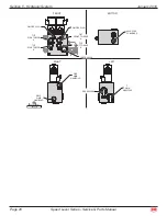
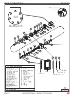
Front Wheel Motors (DT-701)
Refer to page 31.
Housing And Shaft Disassembly
Remove all shaft-related components from the shaft. Secure the motor housing in a vise.
Remove the retaining ring from the grove in the pilot of the housing.
Remove the spacer from the housing.
Remove the shaft from the housing.
Remove the bearing, thrust bearing, and two (2) thrust washers from the shaft.
Being careful not to drop bearing rollers,
Pry out the shaft seal, backup seal, and dust seal from the bearing assembly.
Note:
It is not necessary to remove the metal backup ring from the bearing to service the motor.
Remove the high pressure seal from the groove in the pilot of the housing.
Discard shaft seal, backup seal and high pressure seal.
Clean all parts in an oil-based solvent and dry using compressed air.
Housing And Shaft Assembly
Apply a light coating of fluid to all new seals prior to installation.
Install the high pressure seal into the groove in the pilot of the housing.
Place the shaft on a clean, flat surface with the output end facing up.
Place the first thrust washer, thrust bearing and second thrust washer over the shaft.
Using plastic installation sleeve, place the shaft seal over the shaft with the lip facing down.
Repeat for the backup seal, making sure the lip faces down.
If the metal backup ring came out in Step 2 above, place it over the shaft with the large O.D.
facing down.
Lightly grease the bearing and place it over the shaft with the large O.D. facing down.
Use an arbor press to carefully press the bearing down to press the seal assembly into the
bearing.
Place the shaft assembly into the housing.
Place the dust seal over the shaft with the lip facing up.
Place the bearing spacer and retaining snap ring over the shaft.
Note:
It may be necessary to lightly tap the snap ring and bearing spacer to allow the retaining ring to
seat properly.
1.
•
•
•
•
2.
•
•
•
3.
1.
•
2.
•
•
•
•
•
•
3.
•
•

