"3072RT / 3772RT / 3772RT HD" Service & Parts Manual - ANSI Specifications
March 2008
Page 1-9
•
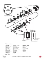
Carefully remove the piston from the endcover and set it aside.
•
Remove and discard the O-ring seal and backup seal.
•
Remove the spring and set it aside.
3. Lift commutator container and commutator from the motor and set aside.
•
Place commutator on a flat, clean surface with the seal facing up.
•
Gently tap on the seal with a small screwdriver until the opposite side of the seal lifts from
the groove. Remove the seal and discard.
4. Remove the manifold, rotor set, and divider plate. Remove all seals and discard.
CAUTION: Do not allow rollers to drop from the rotor assembly when removing the rotor from the
motor.
•
Remove the drive link from the motor and set aside.
5. Clean all parts in an oil-based solvent and dry using compressed air. Apply a light coating
of oil to all new seals prior to installation.
Motor Section Assembly
1. Install the drive link into the end of the shaft with the tapered end facing up.
•
Place the rear housing seal in the groove in the housing.
•
Place the divider plate onto the housing.
•
Place body seals in grooves in both sides of the rotor.
•
Place the rotor onto the housing with the side of the rotor with chamfer in splines facing
the housing.
•
Place the manifold over the rotor with the seal-groove side up.
•
Install the manifold seal
2. Install the commutator seal into the commutator with the metal side facing up.
•
Use finger pressure to press the seal down flush with the surface of the commutator.
•
Place the commutator onto the manifold and then place the commutator onto the protrud-
ing end of the drive link. Make sure that the seal side is facing up.
3. Install the remaining body seal in the groove on the endcover.
•
Install the piston spring into the endcover, then the white backup seal followed by the
O-Ring seal.
•
Line up the alignment pin with the hole in the endcover and press the piston into the
endcover.
•
While holding the piston in place, lower the endcover assembly onto the motor. Align the
“V” shaped marks that were made on the housing and endcover before disassembly.
4. Install the seven (7) assembly bolts.
• Tighten bolts in sequence (see illustration)
•
Pre-torque to 10 ft. lbs. (13,6 Nm).
•
Final torque to 50 ft. lbs (67,8 Nm).
Summary of Contents for 3072RT
Page 40: ...March 2008 3072RT 3772RT 3772RT HD Service Parts Manual ANSI Specifications Page 1 26...
Page 52: ...March 2008 3072RT 3772RT 3772RT HD Service Parts Manual ANSI Specifications Page 2 12...
Page 93: ...3072RT 3772RT 3772RT HD Service Parts Manual ANSI Specifications March 2008 Page 5 9...
Page 96: ...March 2008 3072RT 3772RT 3772RT HD Service Parts Manual ANSI Specifications Page 5 12...


