Page 29
45-J Desel - Servce & Parts Manual
January 2022
Secton 10 - Hydraulc System
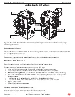
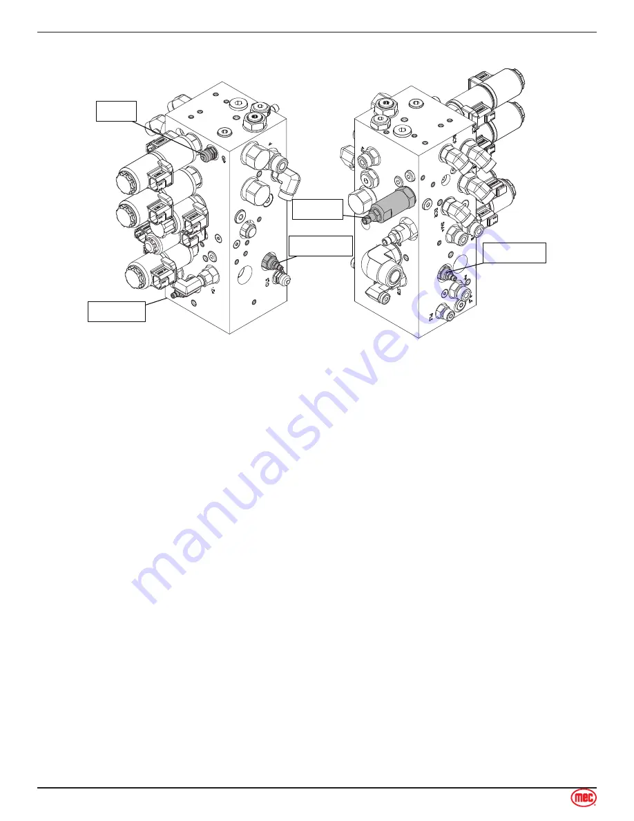
Adjusting Relief Valves
ART_4888
Gauge Port
Main Relief
Valve 6
Steering Cross Port
Relief Valve 3.2
Steering Cross Port
Relief Valve 3.1
Boom Extend
Relief Valve 10
System pressures should be checked and adjusted during routine maintenance to ensure proper
machine performance
Counterbalance Valves
The counterbalance valves located on many of the cylinders are set by the manufacturer and should
not be adjusted for any reason.
Replace any counterbalance valve that shows evidence of adjustment or tampering.
Main Relief Valve Pressure 6
Park the machine on a firm level surface free from overhead obstructions.
Primary Manifold Pressure should be set to 3000 psi (207 bar).
Insert a 0-5000 psi gauge into the port GP of the Main Functions Manifold.
Loosen the lock nut on the Main Relief Valve on the Main Functions Manifold.
With no load on platform
, use the Boom Retract function to retract the boom completely.
Press and hold the Boom Retract switch for 10 seconds to get an accurate reading on the
pressure gauge.
If pressure is LOW, adjust lift relief valve ¼ turn clockwise and recheck.
If pressure is HIGH, adjust lift relief valve ¼ turn counterclockwise and recheck.
Repeat until correct.
Tighten the lock nut on the valve.
Steering Cross Port Relief Valves 3������1, 3������2
Park the machine on a firm level surface free from obstructions.
•
•
•
•
•
•
•
•


