Page 84
45-J Desel - Servce & Parts Manual
January 2022
Secton 18 - Mechancal Components
Swing Bearing/Turntable Components
THIS PROCESS REQUIRES SPECIFIC REPAIR SKILLS AND
EXPERIENCE, APPROPRIATE LIFTING EQUIPMENT AND A PROPER
WORKPLACE������ DEATH, SERIOUS INJURY OR SIGNIFICANT MACHINE
DAMAGE COULD OCCUR IF YOU ATTEMPT THIS PROCESS WITHOUT
THE APPROPRIATE SKILLS AND EQUIPMENT������
The Swing Bearing is located between the turntable and the machine chassis. It’s purpose is to
provide continuous turntable rotation.
Note:
The module doors and module contents are omitted from some of the following illustrations to
better show the disassembly process. It is not necessary to remove the doors or contents to
perform this procedure unless stated.
Disassembly
Park the machine on a firm level surface.
Thoroughly clean all hydraulic connections
and tag all hoses for proper reassembly before
disconnecting them. Immediately plug and cap all
openings to prevent contamination. Tag electrical
connections before disconnecting them.
Remove the Platform/Jib assembly as described in
steps 1 through 12 of the Platform Level Cylinder
removal procedure on page 74.
Disassemble the boom linkage as described in the
Boom Lift Cylinder/Boom Linkage procedure on
page 78.
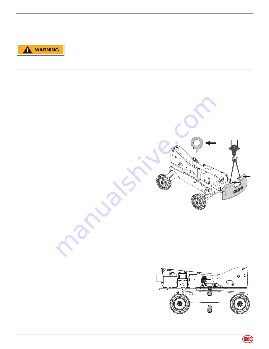
Thread two M24 lifting eyebolts into the machine
counterweight and rig slings as shown. Apply slight
lifting pressure.
1.
2.
3.
4.
5.
ART_4942
M24 Lifting Eye
Minimum
30 mm length
Remove the four bolts that secure the counterweight to the machine turntable.
Remove the counterweight.
Note:
Counterweight Mass: 1980 LBS / 898 KG
Tag and disconnect the hydraulic lines from the top
of the Rotary Manifold.
Tag and disconnect the hydraulic lines from the
bottom of the Rotary Manifold.
Support the Rotary Manifold from below, then
remove the bolts securing the Rotary Manifold in
place.
Remove the Rotary Manifold.
Note:
Rotary Manifold Mass:
75 LBS
34 KG
8.
9.
10.
11.
ART_4944
Rotary
Manifold
6.
7.


