User Manual
in the power supply. Otherwise, even if you only need to connect a single external E-Stop,
you need to properly wire the rest of the connections in the D-SUB connector.
Figure 17 shows the pinout of the D-SUB 15-position connector on the power supply and
gives a generic example for all connections. As already mentioned, you can connect:
- one external Stop Category 1 emergency stop (connections E-Stop A1, E-Stop B1,
E-Stop A2, E-Stop B2);
- one Stop Category 1 protective stop (connections P-Stop 1 A1, P-Stop 1 K1,
P-Stop 1 A2, P-Stop 1 K2);
- one reset button (connections Reset A, Reset K);
- one power status indicator (connections Power Status A, Power Status B);
- one Stop Category 2 protective stop (connections P-Stop 2 A, P-Stop 2 B).
Note that the external circuits shown in Fig. 17 are only suggestions. You may, for
example, connect several external E-Stops in series, or instead of sending a signal to a PLC
when the power to the robot is cut, you may connect a LED between the resistor and the
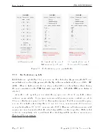
Power Status A line. Figure 18 shows several other examples. Specically, Fig. 18a shows
how to control the protective stop 1 from a PLC by supplying a 24 V DC signal. Figure 18b
shows how to reset the power supply from a PLC. Figure 18c shows that you can supply a
12 mA continuous forward current to pins 4 and 5 if you do not want to use the protective
stop 1. Lastly, Fig. 18d shows that you need to short-circuit pins 1 and 9, and pins 2 and
10, if you do not intend to use an external E-Stop.
Copyright c
2020 by Mecademic Inc.
Page 31 of 38
Summary of Contents for Meca500
Page 43: ......
Page 44: ...Mecademic Inc 1300 Saint Patrick St Montreal QC H3K 1A4 CANADA ...


