User Manual
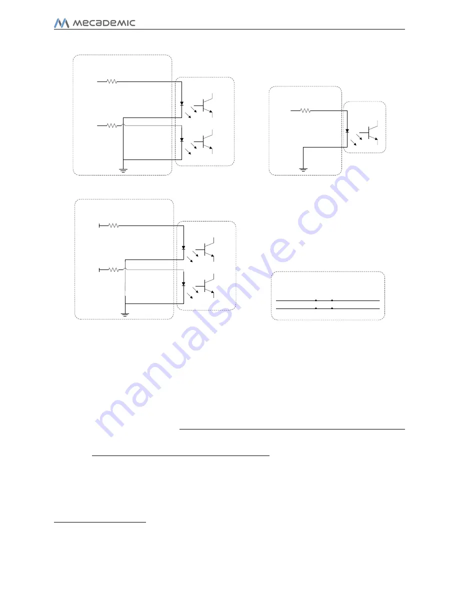
P-Stop 1 – A1 (4)
P-Stop 1 – A2 (5)
P-Stop 1 – K2 (13)
P-Stop 1 – K1 (12)
External protective stop 1
(Stop Category 1)
Inside power supply
24 V PLC
Output
1k
Ω
1k
Ω
24 V PLC
Output
(a) External protective stop from a PLC
Reset – K (15)
Inside power supply
PLC - Reset
1k
Ω
24 V PLC
Output
Reset – A (7)
(b) Reset from a PLC
P-Stop – A1 (4)
P-Stop 1 – A2 (5)
P-Stop 1 – K2 (13)
External protective stop 1, when not used
(Stop Category 1)
Inside power supply
24 V
1k
Ω
1k
Ω
P-Stop 1 – K1 (12)
24 V
(c) External protective stop 1 not used
External E-Stop, when not used
E-Stop – A1 (1)
E-Stop – B1 (9)
E-Stop – A2 (2)
E-Stop – B2 (10)
(d) External E-Stop not used
Figure 18: Additional examples of connections to D-SUB connector
10 Installing an end-eector
The Meca500 comes with a proprietary tool I/O (input/output) port located at the robot
extremity (Fig. 19a). However, this tool port is reserved uniquely for our electric gripper
. We do not share the pinout of this port or its custom-made communication
protocol. To install our gripper, refer to its
If you want to use any other end-eector with the Meca500, you will need to control it
independently from the Meca500. You can attach the cabling of your end-eector along the
robot arm using adhesive-backed tie mounts. Finally, you must x the end-eector to the
robot's ange (Fig. 19b) using four M3 screws and, optionally, one
3
locating pin, all of
properly selected length. The following rules should be respected:
Copyright c
2020 by Mecademic Inc.
Page 33 of 38
Summary of Contents for Meca500
Page 43: ......
Page 44: ...Mecademic Inc 1300 Saint Patrick St Montreal QC H3K 1A4 CANADA ...


