background image

F1050/F1200

1-6

1

Safety regulations

1.5.1.21

Only reliable persons may act as guides. They

must be informed of their duties prior to commencing work.

1.5.1.22

The driver and guide must agree on signals for

communication. These signals may only be given by the
driver and guide.

1.5.1.23

The guide must be easily recognizable – e.g. by

wearing warning clothing – and must always be in the
driver’s field of vision.

1.5.1.24

When passing under subways, bridges, tunnels,

electrical overhead lines, etc., make sure that there is
adequate clearance!

1.5.1.25

Maintain adequate clearance when working at

the edge of quarries, pits, rubbish dumps and embank-
ments to eliminate any danger of the machine plunging
down. The contractor or his deputy must stipulate the
distance from the edge, taking the soil bearing capacity
into consideration.

1.5.1.26

The machine may only be used at stationary

dumping areas when firmly integrated installations are
provided to prevent the machine from running or sliding
down.

1.5.1.27

Avoid such work which could have a detrimental

effect on the stability of the machine.
The following may affect the stability:
- overloading,
- ground that is too soft,
- abrupt acceleration or deceleration of driving or working

movement,

- reversing out of a high driving speed,
- working on slopes,
- driving too quickly round sharp bends,

1.5.1.28

Do not traverse across slopes. Always carry

working equipment and loads near the ground, especially
when driving down slopes. Sudden cornering is forbidden!

1.5.1.29

On steep inclines and gradients, the load is to be

carried on the uphill side.

1.5.1.30

Reduce speed before inclines; always adapt the

speed of the machine to the local conditions!

Never

 change into low gear when driving on slopes, but

rather before the slope!

1.5.1.31

Reversing over a longer period must be avoided!

1.5.1.32

When leaving the machine, always safeguard the

machine to prevent it from unintentionally rolling away;
prevent non-authorised persons from using it!

1.5.1.33

The driver must not leave the machine if the

attachments are not lowered or safeguarded.

1.5.1.34

During breaks and after work hours, the driver

must park the machine on solid and, if possible, level
ground and safeguard it against unintentionally rolling
away.

Summary of Contents for AF 1050

Page 1: ...schinenGmbH AmFriedrichsbrunnen2 D 24782B delsdorf Telefon 49 0 4331 351 325 Internet www mecalac de Telefax 49 0 4331 351 404 E Mail info mecalac de AF1050 AF1200 OPERATINGINSTRUCTIONS FRONTLOADER Tr...

Page 2: ...in as final customer and specify the FIN number truck identification number of your MECALAC truck When you already own an MECALAC truck you can also view the spare parts documentation here To do so p...

Page 3: ...ormation which the user requires for operation and maintenance In the Maintenance section all maintenance work and operation tests are described which can be carried out bytrainedpersonnel Thissection...

Page 4: ...0 F1200 II Table of Contents Abbreviations used UVV Unfallverh tungsvorschrift AccidentPreventionRegulations StVZO Stra enverkehrzulassungsordnung GermanTrafficRegulations Edition 11 2013 Printed 11 2...

Page 5: ...2 1 8 1 Organizationalmeasures 1 12 1 8 2 Selection of personnel and necessary qualifications basic responsibilities 1 12 2 Signs 3 Protection against theft 3 1 Identifyingfeaturesontheloader 3 2 3 2...

Page 6: ...8 1 8 1 Notesregardingmaintenance 8 2 8 2 Maintenancework 8 3 8 2 1 Engine inspections 8 3 8 2 1 1 Engine oil level check 8 3 8 2 1 2 Cooling water check 8 3 8 2 1 3 V belt check 8 4 8 2 1 4 V belt t...

Page 7: ...12 Fuel supply system 11 4 11 1 13 Heaterandventilationsystem 11 4 11 1 14 Suction return flow filter 11 4 11 1 15 Electric contamination indicator 11 4 11 1 16 Combination cooler with temperature con...

Page 8: ...2 2 12 1 1 Buckets 12 2 12 1 2 Fork liftattachment 12 4 12 1 3 Lifting hook 12 4 12 2 AF 1200 12 6 12 2 1 Buckets 12 6 12 2 2 Fork liftattachment 12 8 12 2 3 Lifting hook 12 8 13 Additional options 13...

Page 9: ...Safety regulations...

Page 10: ...neandmanufacturer approvedattach ments may only be used in a technical non objectionable condition taking all safety regulations into account espe cially with regard to the operating manuals machine a...

Page 11: ...ing caught or being pulled in 1 3 6 Allsafetyanddangerplatesonthemachinemust beobserved 1 3 7 All safety and danger plates must be attached to the machine and must be kept legible 1 3 8 Incaseofmodifi...

Page 12: ...must not be transported 1 5 1 2 Startanddrivethemachinefromthedriver sseat only 1 5 1 3 Observethecontrollampsaccordingtotheopera tion manual machine and engine during starting and switching offoperat...

Page 13: ...our immediatelytothepersonincharge Ifnecessary stopthe machine immediately and secure it 1 5 1 15 Thedrivermayslewtheattachmentsinoverhead driving operatingandworkingareasonlyiftheseareasare suitablys...

Page 14: ...h work which could have a detrimental effect on the stability of the machine The following may affect the stability overloading ground that is too soft abruptaccelerationordecelerationofdrivingorworki...

Page 15: ...tachment is set down on the ground or supported or when equivalent measures against uninten tional movement were taken Duringmaintenanceandrepairworkunderthebucketarm the bucket arm must be mechanical...

Page 16: ...f mainte nanceworkandmakesurethatthemachineisfreefromoil fuel oil or dirt Do not use aggressive detergents Use lintless cleaning rags 1 5 2 17 Beforecleaningthemachinewithwaterorsteam jet high pressur...

Page 17: ...rance kilovolts meters to 1 kV 1 0 m above 1 kV to 110 kV 3 0 m above110 kV to 220 kV 4 0 m above220 kV to 380 kV 5 0 m unknownnominalvoltage 5 0 m Whenapproachingoverheadlines allworkingmovements of...

Page 18: ...smust be checked regularly for leakages and visible damage Immediately repair such defects Spurting hydraulic oil may cause injuries and fire 1 6 2 3 Those hydraulic system segments which are to beope...

Page 19: ...ng and grinding work on the machine only when this is explicitly approved Other wise there is the danger of fire and explosion 1 6 5 3 Beforecarryingoutwelding burningandgrinding work clean the machin...

Page 20: ...it a warning triangle and a warning lamp must be available on thevehicle 1 8 2 Selectionofpersonnelandnecessary qualifications basicresponsibilities 1 8 2 1 Onlyreliablepersonsareallowedtoworkon with...

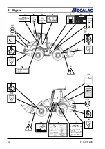
Page 21: ...Signs...

Page 22: ...r kW Fahrzeug Identifi zierungs Nr FIN Motor leistung Typ Ausf zul Achslast hinten zul Achslast vorn zul Gesamtgewicht Betriebserlaubnis Nr 2 1 Baumaschinen GmbH D 24782 B delsdorf kg kg kg 17 1 CAUTI...

Page 23: ...int to the front Floating position 4 Symbol Read and observe the operating instructions before commissioning Make sure that all other users have read the safety instructions 5 Symbol Fuel tank 6 Machi...

Page 24: ......

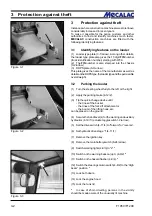
Page 25: ...Protection against theft...

Page 26: ...Stype theloadertypeandthepermissible overallweight 3 2 Parking the loader 1 Turn the steering wheel fully to the left or the right 2 Apply the parking brake 4 12 2 3 Tip the quick change device until...

Page 27: ...es in case of an insured event The transponder for drive away interlock meets the new stricter requirements of the insurance companies Ask your insurance company for the appropriate details 3 3 2 Enco...

Page 28: ...F1050 F1200 3 4 3 Protection against theft...

Page 29: ...Description...

Page 30: ...4 Deflectionlever 5 Tip cylinder 6 Lift cylinder 7 Compensationcylinder 8 Driver scab 9 Battery right truck side behind maintenance flap 10 Drivemotor 11 Hydraulic oil tank filler neck underneath the...

Page 31: ...king value 100 is special equipment Tyres The following tyres are permitted AF1050 AF1200 16 70 R 20 16 70 R 20 405 70 R 20 405 70 R 20 420 75R20 420 75R20 500 45 22 5 500 45 22 5 550 45 R 22 5 550 45...

Page 32: ...ouble acting gear type pump drives two lifting cylinders one tip cylinder one compensation cylinder All movements of the bucket arm the bucket the attach mentsandthequick changedevicearecontrolledfrom...

Page 33: ...r screen 2 large hinged engaging external rear view mirrors tinted rooflight height and inclinationadjustablesteeringcolumn ergonomicadjust able joystick controls sunshade heater and fresh air systemw...

Page 34: ...9 Fit a suitable jack minimum capacity 2 0 tons from the side under the axle bridge in the vicinity of the axle fixture so that it is centred and cannot slip 4 7 Lift the front rearaxleuntilthewheeldo...

Page 35: ...ton for release of quick change device 7 Bucket position indicator NOTE Withtheindicatorlamplitpermanently thebucket floor is parallel to the ground 1 Multifunctionpanel see chapter 4 4 1 Fig 4 14 2 T...

Page 36: ...button Lockattachment Closemultipurposebucket Lowerpushbutton Unlockattachment in conjunction with 4 8 6 Openmultipurposebucket 3 Actuator for differential lock option 4 Driveswitch forward 0 reverse...

Page 37: ...11 Indicator lamp Parking brake 12 free 13 Hydraulic oil filter clogging indicator 14 Warning lamp hydraulic oil temperature 15 Air filter clogging indicator 16 free 17 Indicator lamp Differential loc...

Page 38: ...Warning beacon opt 2 pole socket 10 0 A 3 Working lights front 20 0 A 4 Working lights rear 15 0 A 5 Traction drive steering 20 0 A 6 Hydraulics 20 0 A 7 Turn indicator 7 5 A 8 Windshield wiper washer...

Page 39: ...motor 20 0 A 11 Engine shut off 10 0 A 12 18 free 19 Working lights front 20 0 A 20 Working lights rear 15 0 A 21 free 22 Drive away interlock 5 0 A 23 2 pole socket 15 0 A 24 Radio Interior lighting...

Page 40: ...it CLOSED option K21 2nd auxiliary hydraulics circuit OPEN option K22 1stauxiliaryhydraulicscircuit CLOSED option K23 1st auxiliary hydraulics circuit OPEN option K24 Transmission controller PLC fast...

Page 41: ...ghts up with both gear stages and with gear stage I the indicator lamp Alpha max 4 16 3 lights up additionally 4 6 2 Fast loader 40 km h For the fast loader you can choose between gear stages 1 and 2...

Page 42: ...gearstagethegearswitchwasinbeforechanging NOTE The gear stage engages approx 5 seconds after the loader has come to a standstill When the engine is restarted the gear stage selected at engine shut dow...

Page 43: ...Operation...

Page 44: ...drive switch 4 11 4 to 0 starter interlock 3 Insert the ignition key into the starter switch 4 10 7 and turn the key clockwise to position I 5 1 NOTE Theindicatorlampsforbatterycharge parking brake a...

Page 45: ...e useddowntotemperaturesof20 C super grade dieselfuel If the temperature is below 15 C or 20 C paraffin oil must be added to the diesel fuel For the mixture ratio refer to the diagram 5 2 I Summer die...

Page 46: ...oad lights which are used solely to light up the road are switched on the highest permissible speed is 30 km h Accordingto 52 4 No 1oftheGermanMotor VehicleConstructionandUseRegulations the warning be...

Page 47: ...rator pedal CAUTION The service brake is activated by depressing the brake pedal 4 8 1 Changing the travel direction during driving is notallowedtoavoidputtingotherroadusersat risk 5 2 4 Working with...

Page 48: ...If the hydraulic oil temperature indicator lamp 4 14 13 lightsupduringoperation theloader must be switched off immediately the cause mustbedeterminedbyahydraulicsexpertand the malfunction must be eli...

Page 49: ...5 3 2 Switching off the diesel engine CAUTION If the diesel engine is very hot or has been subjected to heavy loads let the engine idle for a short time before switching it off Turn the ignition key...

Page 50: ...g the weightadjustmentlever Thesetdriver sweightisvisiblein the inspection window 5 9 2 Heightadjustment The height can be adjusted in several steps Lift the driver s seat to the desired height until...

Page 51: ...gthebackrest Use the locking lever 5 13 arrow to adjust the backrest NOTE The locking lever must engage in the desired position It must be impossible to move the backrest to another position when the...

Page 52: ...ravel adjustment 5 15 4 You can increase or reduce the suspension travel by turning the adjusting knob 5 15 4 5 Weight adjustment 5 15 5 Toadjusttothedriver sweight turntheweightadjustment lever 5 15...

Page 53: ...g over The all wheel steering indicator is lit permanently NOTE Crab steering all wheel steering with offset axles is active 4 Switching from crab steering to rear wheel steering The all wheel steerin...

Page 54: ...e all wheel steering indicator lights up the rear wheel steering indicator flashes Turn the steering wheel until the front axle is in straight ahead position Theindicatorfor allwheelsteering goesdarkw...

Page 55: ...Attachments...

Page 56: ...up the bucket using the quick change device and by simultaneously tilting the quick change device raise the bucket until the quick change device is next to it 6 2 4 Lockthebucket 6 3 withtheupperpush...

Page 57: ...his will build up a pressure in the hydraulic cylinder that makes it muchmoredifficulttoconnectthehydrauliclines to the hydraulic connectors later Toavoidthisissue werecommendthefollowing procedureofd...

Page 58: ...ve the shunting and towing coupling To do so loosen the four fastening screws of the shunting and towing coupling and remove them together with the shunting and towing coupling NOTE Givedirectionstoth...

Page 59: ...lic or electric connection Dismounting To dismount proceed in the reverse order of steps 6 4 Use of additional attachments DANGER 1 Only those attachments described in these operating instructions may...

Page 60: ......

Page 61: ...Rescue towing lashing lifting by crane...

Page 62: ...em or if only the drive has failed and the engine can drive the rest of the hydraulic system 7 1 1 1 Towing the front loader if the engine has failed 1 Actuatethetoggleswitchforthehazardflasher 4 9 4...

Page 63: ...ting gear Collect the escaping hydraulic oil in a sufficiently large oil pan After towing has been completed fill the lifting cylinders with hydraulic oil and deaerate them byraisingandloweringthebuck...

Page 64: ...4 2 must be performed in the same way as tightening them In other words you must synchronouslyrepeatlooseningallthreescrews aftereach1 2turntopreventseizingorcanting Loosen the springs at the left and...

Page 65: ...ket protector 5 4 arrow 6 Insert the plug of the bucket protector into the socket 5 5 arrow option 7 Lift and mechanically prop up the bucket arm e g by insertingthebucketarmsupport option 1 1 arrow a...

Page 66: ...parking brake 4 12 2 4 Liftorlowerthebucketarmuntilthelowestpointofthe bucketarmorofthebucketisatleast30 cmabovetheroad 5 4 5 Set the toggle switch for switching off pilot control 4 10 2 to up 6 Lock...

Page 67: ...Maintenance...

Page 68: ...ution gear oil 3 Front axle 3 1 Check axis transmission oil level check plug 3 2 Change axis transmission oil 3 3 Check planetary gear transmission oil level check plug 3 4 Change planetary gear oil 4...

Page 69: ......

Page 70: ...arm Perform maintenance work when the loader is on level ground and the bucket arm is in its lowest position Replace damaged filter inserts and gaskets immediately Clean force feed lubrication nipples...

Page 71: ...ust be between the two markings L low min and H high max If necessary top up oil via the filler neck 8 3 arrow 8 2 1 2 Cooling water check CAUTION Checkthecoolingwaterlevelevery10operating hours 1 Ope...

Page 72: ...alternator every 1500 operating hours 3 Check the adjustment of the tip levers first time after 250 operating hours then every 2000 operating hours inlet valve 0 35 mm outletvalve 0 50 mm 8 2 2 Oil l...

Page 73: ...sary fill oil into the plug bore 8 9 arrow until the oil reaches the required level 2 Fit a new gasket and screw the plug back in 8 2 3 Oil level check Hydraulic oil reservoir 1 Park the loader in a l...

Page 74: ...se the drain screw 8 11 1 CAUTION Tighten the drain plug by hand only to prevent damage to the thread 8 2 4 2 Replacing the fuel filter CAUTION Replace the fuel filter every 500 operating hours or eve...

Page 75: ...echseln GEFAHR Kraftstoff ist entz ndlich Bei Arbeiten an der Kraftstoffanlage sind keine Zigaretten offene Flammen oder sonstige entflammbare Verursacher zul ssig Auf ausreichende Bel ftung ist zu ac...

Page 76: ...Milky oil indicates blending with coolant Heed the stipulated oil change intervals in order to maintain the oil quality CAUTION Waste oil must be disposed of in such a way that it will not cause poll...

Page 77: ...Lubricatethesealofthenewengineoilfiltercartridge with clean engine oil 6 Screw the new filter cartridge in place and give it half a turn to tighten it heed the manufacturer s notes CAUTION Take care n...

Page 78: ...reachestheopening NOTE Information about the quantity of oil is given in the maintenance plan chapter 8 4 After a few minutes when the oil level has lowered top up the oil until the oil reaches the ma...

Page 79: ...erneath 2 Unscrewtheplugsfromtheaxlearch 8 22 arrowsand 8 23 arrow and drain the oil CAUTION Waste oil must be disposed of in such a way that it will not cause pollution 3 Screw in the plug 8 23 arrow...

Page 80: ...the marked level and remains stable The vent valve of the axle 8 25 arrow must be free from dirt 5 Screw in the plug 8 24 1 again with a new gasket 8 2 8 Oil change hydraulic system 1 Have an oil drai...

Page 81: ...filling nozzle 8 2 9 Changing the hydraulic oil filter in sert CAUTION Replace the filter insert according to the maintenanceplanorwhenthecloggingindicator lamp 4 14 13 lights up NOTE The clogging in...

Page 82: ...ed when the air filter clogging indicator 4 14 15 lights up but at the latest after 12 months 1 Open the motor hood 2 Loosenthethreespring loadedcatchesontheairfilter lid 8 30 arrows and remove the ai...

Page 83: ...the filter cartridge section 8 2 10 2 Pierce the seal of the safety cartridge 8 32 arrow from the inside by using a screwdriver or similar tool and pull up both strips 3 Hold the safety cartridge by b...

Page 84: ...compensation tank When topping up brake hydraulic oil use only hydraulic oil acc to DIN 51524 HVLP 46 of viscosity class ISO VG 46 VI 180 NOTE The compensation tank for the brake hydraulic oil 8 35 ar...

Page 85: ...F1050 F1200 8 17 Maintenance 8 Figure 8 39 Figure 8 40 Bottom of compensation cylinder Piston side of tip cylinder Bottom of tip cylinder Figure 8 38...

Page 86: ...ever 8 3 2 Rear axle CAUTION The spindle bolts must be lubricated every 10 operatinghours NOTE Lubricate the top and the bottom of the axle spindle bolts on both sides of the axle 8 42 arrows 8 3 3 Re...

Page 87: ...ides of the axle 8 3 5 Engine hood CAUTION Thehingesoftheenginehoodmustbelubricated every 50 operating hours 8 3 6 Multi purpose bucket CAUTION The bearing bolts of the multi purpose bucket must be lu...

Page 88: ...F1050 F1200 8 20 8 Maintenance Figure 8 47...

Page 89: ...Circuit diagrams...

Page 90: ...ique Wiring diagramm Elektrisch schakelschema S hk kytkent kaavio Variante 1 Kopplingsschema elektrik Schemat instalacji elektrycznej Sch ma elektrick ho zapojen El diagram F1050 F1200 S0700 S0900 10...

Page 91: ...dicator 1 4 5 Actuator rearwindowwiper washer 1 4 6 Actuator Rear window heater 1 4 7 Actuator release of quick change device 1 4 8 Actuator working lights 1 4 9 Actuator warning beacon opt 1 4 10 Act...

Page 92: ...Relay K18 Dump interlock 2 4 17 Relay K24 Dump interlock timer 2 4 18 Turn signal relay 2 4 19 Intervaltimer 2 4 20 Fuse F16 High beam 15 0 A 2 4 21 Fuse F13 Parking light left tail light left 5 0 A...

Page 93: ...schakelschema S hk kytkent kaavio Variante 1 Kopplingsschema elektrik Schemat instalacji elektrycznej Sch ma elektrick ho zapojen El diagram 1 4 4 4 3 4 10 4 F1050 F1200 S0700 S0900 2 4 1 2 3 4 5 6 7...

Page 94: ...rik Schemat instalacji elektrycznej Sch ma elektrick ho zapojen El diagram 3 4 2 4 10 5 F1050 F1200 S0700 S0900 18 12 13 14 15 16 17 19 20 21 22 23 24 25 26 27 28 29 31 32 33 1 2 3 4 5 6 7 8 9 10 11 3...

Page 95: ...41 Proximity switch Boost 3 4 42 Working lights centre support 3 4 43 Working lights lifting arm 3 4 44 Working lights lifting arm 3 4 45 Combinationvalve pipebreakprotection liftingdevicesuspension o...

Page 96: ...4 4 16 Turn signal left For AS 700 only 4 4 17 Windshield wiper motor rear 4 4 18 Interiorlighting 4 4 19 Switch Interior lighting 4 4 20 Rearwindowheater opt 4 4 21 Working lights rear 4 4 22 Working...

Page 97: ...h schakelschema S hk kytkent kaavio Variante 1 Kopplingsschema elektrik Schemat instalacji elektrycznej Sch ma elektrick ho zapojen El diagram 2 4 10 6 F1050 F1200 S0700 S0900 4 4 17 25 26 23 20 18 21...

Page 98: ...g diagramm Elektrisch schakelschema S hk kytkent kaavio Variante 3 Kopplingsschema elektrik Schemat instalacji elektrycznej Sch ma elektrick ho zapojen El diagram F1050 F1200 S700 S900 T1050 ST900 10...

Page 99: ...6 Actuator rear window wiper washer 1 6 7 Actuator Rear window heater 1 6 8 Actuator release of quick change device 1 6 9 Actuator working lights 1 6 10 Actuator warning beacon opt 1 6 11 Actuator Haz...

Page 100: ...2 6 12 Fuse F8 Working lights front 15 0 A 2 6 13 Fuse F9 Working lights rear 15 0 A 2 6 14 Fuse F10 Drive away interlock 5 0 A 2 6 15 Fuse F11 2 pole socket 15 0 A 2 6 16 Fuse F12 Radio interior lig...

Page 101: ...kelschema S hk kytkent kaavio Variante 3 Kopplingsschema elektrik Schemat instalacji elektrycznej Sch ma elektrick ho zapojen El diagram 1 6 3 6 5 6 10 13 2 6 6 6 F1050 F1200 S700 S900 T1050 ST900 2 3...

Page 102: ...gramm Elektrisch schakelschema S hk kytkent kaavio Variante 3 Kopplingsschema elektrik Schemat instalacji elektrycznej Sch ma elektrick ho zapojen El diagram 10 14 3 6 2 6 4 6 F1050 F1200 S700 S900 T1...

Page 103: ...nd auxiliary hydraulics circuit open option 3 6 10 Relay K22 1st auxiliary hydraulics circuit closed option 3 6 11 Relay K23 1st auxiliary hydraulics circuit open option 3 6 12 Relay K16 Fan control 3...

Page 104: ...switch off 4 6 16 Actuator lifting device suspension option 4 6 17 Actuator Permanent auxiliary hydraulics opt 4 6 18 Actuator Dump interlock switch off 4 6 19 Actuator pilot control switch off 4 6 20...

Page 105: ...S hk kytkent kaavio Variante 3 Kopplingsschema elektrik Schemat instalacji elektrycznej Sch ma elektrick ho zapojen El diagram 4 6 10 15 3 6 F1050 F1200 S700 S900 T1050 ST900 16 15 26 27 28 30 30 31...

Page 106: ...i elektrycznej Sch ma elektrick ho zapojen El diagram Schemat elektryczny 68 65 64 67 55 57 60 66 58 54 69 21 19 20 56 53 59 23 16 17 24 25 30 13 14 1 2 3 4 5 7 8 9 10 11 12 15 18 22 26 27 28 29 31 35...

Page 107: ...43 Proximity switch Dump interlock raise 5 6 44 Working lights front end front loader 5 6 45 Working lights front end front loader 5 6 46 Working lights lifting arm swivel loader 5 6 47 Working lights...

Page 108: ...d gear 6 6 19 Valve 1st gear 6 6 20 Valve four wheelsteering 6 6 21 Valve rear axle steering 6 6 22 Valve Parking brake 6 6 23 Pressure switch inching 6 6 24 Valve Dump interlock 6 6 25 Switch Brake l...

Page 109: ...sch schakelschema S hk kytkent kaavio Kopplingsschema elektrik Schemat instalacji elektrycznej Sch ma elektrick ho zapojen El diagram T1050 10 17 6 6 2 6 3 4 16 14 15 17 22 12 13 6 1 2 7 8 9 10 11 20...

Page 110: ...elschema S hk kytkent kaavio Kopplingsschema elektrik Schemat instalacji elektrycznej Sch ma elektrick ho zapojen El diagram ST900 10 18 6 6 2 6 3 4 16 14 15 17 22 12 13 6 1 2 7 8 9 10 11 20 18 19 21...

Page 111: ...g brake 6 6 23 Pressure switch inching 6 6 24 Valve Dump interlock 6 6 25 Valve Permanent auxiliary hydraulics 6 6 26 Switch Brake lights 6 6 27 Tacho sensor 6 6 28 Switch Parking brake 6 6 29 Dip pip...

Page 112: ...kaavio Schemat hydrauliczny Hydraulikdiagram AF 1050 AF 1200 Messanschluss Branchement de mesure Gauge part Meetaansluiting Sonderausstattung En option Optional equipment Wardt niet standaard geleverd...

Page 113: ...13 Doubleshockvalve 14 Steeringswitchingvalve 15 Blockingvalve 16 Differentiallockvalve 17 Steering unit 320 160 cm rev 18 Priorityvalve 19 Drive motor A6VM 115 HA 20 Gear type pump 32 8 cm rev 21 Dr...

Page 114: ......

Page 115: ...Technical Data Equipment...

Page 116: ...ngine 8 000 kg unbraked 750 kg Max lifting capacity 54 0 kN with Boost 65 0 kN Max thrust force 46 5 kN 11 1 2 Engine 11 1 2 1 49 kW engine Liquid cooled diesel engine 4 cylinders 4 stroke indirect in...

Page 117: ...ze 16 70 R 20 MPT 04 Tyre pressure front 3 0 bar rear 3 0 bar Size 405 70 R 20 XZSL Tyre pressure front 3 75 bar rear 3 75 bar Size 405 70 R 20 EM 01 Tyre pressure front 3 75 bar rear 3 75 bar Size 40...

Page 118: ...system Air water heat exchanger Heater performance 3 stage heater max 14 5 kW Air flow 3 stage blower max 1 000 m h Electric power 250 W 11 1 14 Suction return flow filter Filter mesh 10 m nom Bypass...

Page 119: ...kg Max lifting capacity 66 0 kN with Boost 77 0 kN Max thrust force 48 5 kN 11 2 2 Engine 11 2 2 1 55 kW engine Liquid cooled diesel engine 4 cylinders 4 stroke indirect injection Displacement 3 260...

Page 120: ...ure front 3 0 bar rear 3 0 bar Size 405 70 R 20 XZSL Tyre pressure front 3 75 bar rear 3 75 bar Size 405 70 R 20 EM 01 Tyre pressure front 3 75 bar rear 3 75 bar Size 9 00 R 20 X MINE D2 Tyre pressure...

Page 121: ...system Air water heat exchanger Heater performance 3 stage heater max 14 5 kW Air flow 3 stage blower max 1 000 m h Electric power 250 W 11 2 14 Suction return flow filter Filter mesh 10 m nom Bypass...

Page 122: ......

Page 123: ...TechnicalData Attachments...

Page 124: ...F1050 F1200 12 2 12 Technical Data Attachments G L H6 D B L6 H8 J HH13 HH12 H5 A A 2 H10 12 1 AF 1050 NOTE The technical data refer to 16 70 R 20 tyres 12 1 1 Buckets...

Page 125: ...mm 6 030 6 070 A2 Dumpangle 45 45 B Max dumping distance at dumping angle 45 mm 1 580 1 790 G Dumping height at max dumping distance and dumping angle 45 mm 890 780 H5 Ground clearance cardan shaft m...

Page 126: ...F1050 F1200 12 4 12 Technical Data Attachments L8 D C B A 5 H6 G HH15 HH9 500 N EE DD HH0 12 1 2 Fork lift attachment 12 1 3 Lifting hook...

Page 127: ...y factor 1 67 kg Perm payload N acc to EN 474 3 fork lift attachment 300 mm above ground steered level ground stability factor 1 25 2 870 kg uneven ground stability factor 1 67 kg A5 Tilt angle 18 B M...

Page 128: ...F1050 F1200 12 6 12 Technical Data Attachments G L H6 D B L6 H8 J HH13 HH12 H5 A A 2 H10 12 2 AF 1200 NOTE The technical data refer to 16 70 R 20 tyres 12 2 1 Buckets...

Page 129: ...gth mm 6 080 6 120 A2 Dumpangle 45 45 B Max dumping distance at dumping angle 45 mm 1 610 1 820 G Dumping height at max dumping distance and dumping angle 45 mm 875 765 H5 Ground clearance cardan shaf...

Page 130: ...F1050 F1200 12 8 12 Technical Data Attachments L8 D C B A 5 H6 G HH15 HH9 500 N HH0 EE DD 12 2 2 Fork lift attachment 12 2 3 Lifting hook...

Page 131: ...d stability factor 1 67 kg Perm payload N acc to EN 474 3 fork lift attachment 300 mm above ground steered level ground stability factor 1 25 3 150 kg uneven ground stability factor 1 67 kg A5 Tilt an...

Page 132: ......

Page 133: ...Optional Extras...

Page 134: ...al situations requiring a high engine speed at low travel speed such as rotary brush trench cutting machine etc you may have to select gear stage I and inching speed 1 Start the engine 2 Pick up the a...

Page 135: ...F1050 F1200 13 3 Optional Extras 13...

Page 136: ...F1050 F1200 13 4 13 Optional Extras...

Page 137: ...F1050 F1200 13 5 Optional Extras 13...

Page 138: ...F1050 F1200 13 6 13 Optional Extras...

Page 139: ...F1050 F1200 13 7 Optional Extras 13...

Page 140: ...F1050 F1200 13 8 13 Optional Extras...

Page 141: ...F1050 F1200 13 9 Optional Extras 13...

Page 142: ...F1050 F1200 13 10 13 Optional Extras...

Page 143: ...F1050 F1200 13 11 Optional Extras 13...

Page 144: ...F1050 F1200 13 12 13 Optional Extras...

Page 145: ...F1050 F1200 13 13 Optional Extras 13...

Page 146: ...F1050 F1200 13 14 13 Optional Extras...

Page 147: ...F1050 F1200 13 15 Optional Extras 13...

Page 148: ...F1050 F1200 13 16 13 Optional Extras 23131461 KL C 31632...

Reviews:

Related manuals for AF 1050