F1050/F1200
4-4
4
Description
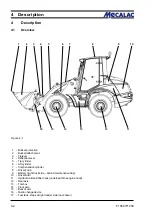
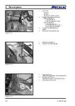
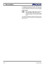
Figure 4-4
Figure 4-3
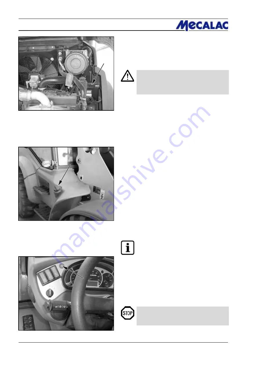
Battery
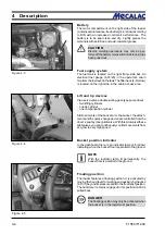
The motor compartment on the right side of the loader
contains a maintenance-free battery (4-3/arrow) according
to DIN with an increased cold start performance. The
battery is to be kept clean and dry. Lightly grease the
terminals with acid-free and acid-resistant grease.
CAUTION
Electric welding operations may only be per-
formed if the battery main switch (8-24/arrow) has
been pulled out.
Fuel supply system
The fuel tank is located on the right frame side bar. An
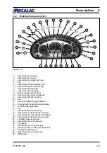
electrical fuel gauge (4-14/23) in the operator’s cabin
monitors the fuel level in the tank. The filler neck (4-4/arrow)
is located on the right side in the cabin access area.
Lift and tip devices
Via a servo valve a double-acting gear-type pump drives
- two lifting cylinders
- one tip cylinder
- one compensation cylinder
All movements of the bucket arm, the bucket, the attach-
ments and the quick-change device are controlled from the
driver’s seat by (one) pilot valve. With this pilot valve/these
pilot valves, you can continuously control movements from
very low to very high speed.
Bucket position indicator
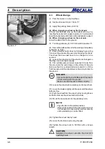
In the dashboard there is an indicator lamp (4-5/arrow)
indicating when the bucket floor is parallel to the ground.
NOTE
With the indicator lamp lit permanently, the
bucket floor is parallel to the ground.
Floating position
The loader features a floating position. It is activated by
moving the hand lever for working and auxiliary hydraulics
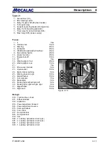
(4-10/1) beyond its pressure point to the frontmost position.
The hand lever remains engaged in this position until it is
pulled back.
DANGER
The floating position may only be activated when
the bucket is in the lowermost position.
Figure 4-5
Summary of Contents for AF 1050
Page 9: ...Safety regulations...
Page 21: ...Signs...
Page 24: ......
Page 25: ...Protection against theft...
Page 28: ...F1050 F1200 3 4 3 Protection against theft...
Page 29: ...Description...
Page 43: ...Operation...
Page 55: ...Attachments...
Page 60: ......
Page 61: ...Rescue towing lashing lifting by crane...
Page 67: ...Maintenance...
Page 69: ......
Page 88: ...F1050 F1200 8 20 8 Maintenance Figure 8 47...
Page 89: ...Circuit diagrams...
Page 114: ......
Page 115: ...Technical Data Equipment...
Page 122: ......
Page 123: ...TechnicalData Attachments...
Page 132: ......
Page 133: ...Optional Extras...
Page 135: ...F1050 F1200 13 3 Optional Extras 13...
Page 136: ...F1050 F1200 13 4 13 Optional Extras...
Page 137: ...F1050 F1200 13 5 Optional Extras 13...
Page 138: ...F1050 F1200 13 6 13 Optional Extras...
Page 139: ...F1050 F1200 13 7 Optional Extras 13...
Page 140: ...F1050 F1200 13 8 13 Optional Extras...
Page 141: ...F1050 F1200 13 9 Optional Extras 13...
Page 142: ...F1050 F1200 13 10 13 Optional Extras...
Page 143: ...F1050 F1200 13 11 Optional Extras 13...
Page 144: ...F1050 F1200 13 12 13 Optional Extras...
Page 145: ...F1050 F1200 13 13 Optional Extras 13...
Page 146: ...F1050 F1200 13 14 13 Optional Extras...
Page 147: ...F1050 F1200 13 15 Optional Extras 13...
Page 148: ...F1050 F1200 13 16 13 Optional Extras 23131461 KL C 31632...

