AF1050/AF1200
7-5
Rescue, towing, lashing,
7
lifting by crane
7.1.1.2 Towing the front loader if the propul-
sion drive has failed
(1) Actuate the toggle switch for the hazard flasher (4-9/4).
(2) Apply the parking brake (4-12/2).
CAUTION
If the rescue location is on a slope, wheel chocks
must be placed on the sloping side of both front
axle wheels in addition to applying the parking
brake.
(3) Set the drive switch (4-11/4) to “0”.
NOTE
The preparations described in steps (5), (6)
and (8) are only to be carried out if the rescue
location is
not
on a public road:
(4) Switch the switching lever for the steering to the „rear-
wheel steering“ position (chapter 5.5).
(5) Cover the bucket cutting edge and teeth with the
bucket protector (5-4/arrow).
(6) Insert the plug of the bucket protector into the socket
(5-5/arrow, option).
(7) Lift and mechanically prop up the bucket arm [e.g. by
inserting the bucket arm support (option) (1-1/arrow)] and
lower the bucket arm until it rests on the bucket arm support.
(8) Set the toggle switch for switching off pilot control
(4-10/2) to
„up“
.
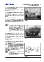
(9) Connect the tow rod to the loader to be towed (7-2/
arrow) and to the towing vehicle.
CAUTION
The loader does not have a shunting and towing
coupling at the front and for this reason may
only be towed rearwards.
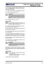
(10) Switch the hydrostatic drive motor to free oil flow
before towing. To do so, turn out the two-way valve
(7-3/1) with an Allen key (size 8) all the way to the left
(7-3/2).
NOTE
- Turn the two-way valve (7-3/1) back in when
towing is finished.
- The traction drive is located in the engine
compartment on the left side.
(11) Remove the chocks (if applicable).
Summary of Contents for AF 1050
Page 9: ...Safety regulations...
Page 21: ...Signs...
Page 24: ......
Page 25: ...Protection against theft...
Page 28: ...F1050 F1200 3 4 3 Protection against theft...
Page 29: ...Description...
Page 43: ...Operation...
Page 55: ...Attachments...
Page 60: ......
Page 61: ...Rescue towing lashing lifting by crane...
Page 67: ...Maintenance...
Page 69: ......
Page 88: ...F1050 F1200 8 20 8 Maintenance Figure 8 47...
Page 89: ...Circuit diagrams...
Page 114: ......
Page 115: ...Technical Data Equipment...
Page 122: ......
Page 123: ...TechnicalData Attachments...
Page 132: ......
Page 133: ...Optional Extras...
Page 135: ...F1050 F1200 13 3 Optional Extras 13...
Page 136: ...F1050 F1200 13 4 13 Optional Extras...
Page 137: ...F1050 F1200 13 5 Optional Extras 13...
Page 138: ...F1050 F1200 13 6 13 Optional Extras...
Page 139: ...F1050 F1200 13 7 Optional Extras 13...
Page 140: ...F1050 F1200 13 8 13 Optional Extras...
Page 141: ...F1050 F1200 13 9 Optional Extras 13...
Page 142: ...F1050 F1200 13 10 13 Optional Extras...
Page 143: ...F1050 F1200 13 11 Optional Extras 13...
Page 144: ...F1050 F1200 13 12 13 Optional Extras...
Page 145: ...F1050 F1200 13 13 Optional Extras 13...
Page 146: ...F1050 F1200 13 14 13 Optional Extras...
Page 147: ...F1050 F1200 13 15 Optional Extras 13...
Page 148: ...F1050 F1200 13 16 13 Optional Extras 23131461 KL C 31632...

